A bubble pump structure

A technology of bubble pump and hose, applied in the field of pump structure, can solve problems such as difficulties in making pumps, inability to make full use of advantages, and large size gaps

Active Publication Date: 2017-01-11
江阴智产汇知识产权运营有限公司
View PDF2 Cites 0 Cited by
  • Summary
  • Abstract
  • Description
  • Claims
  • Application Information

AI Technical Summary

Problems solved by technology

However, although there are many types and applications of pumps at present, and the size gap is very large, when the scale of the entire system is reduced to the millimeter level, it is quite difficult to manufacture pumps with the current traditional processing methods.
This leads to the difficulty of constructing and studying hydraulic systems at the millimeter level, with little understanding of their characteristics and an inability to take full advantage of them

Method used


Image

  • A bubble pump structure
  • A bubble pump structure
  • A bubble pump structure

Examples


Embodiment Construction

[0011] The technical solutions of the present invention will be described in further detail below in conjunction with the accompanying drawings and specific embodiments.

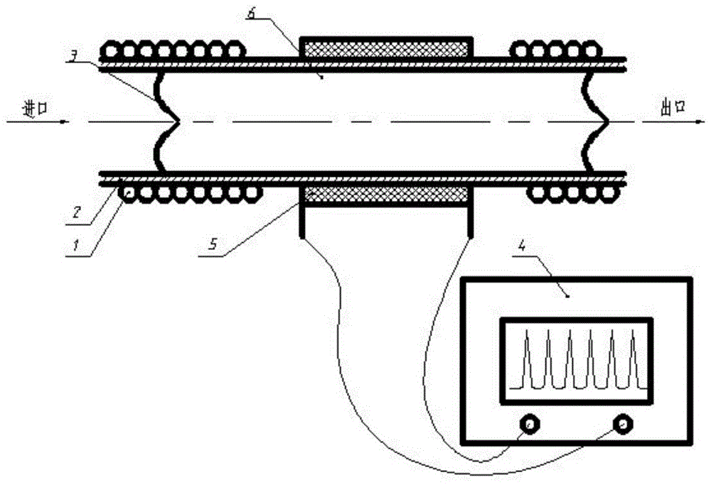
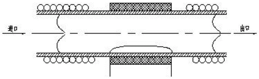
[0012] The structure diagram of the present invention is as figure 1 and Figure 1-A shown. The present invention is mainly designed by using the pressure change caused by the volume change of the positive displacement pump to realize the working principle of pumping and discharging liquid. As shown in Figure 2, the pulse signal generator first adds a voltage pulse to the thin film resistance heater, so that It heats the liquid in the tube. Due to the high heat flux density, the heating speed is extremely fast. In a short time, the liquid near the surface of the heater is heated up rapidly, reaching its boiling temperature, and the liquid is vaporized to form bubbles, as shown in Figure 2 -As shown in Figure 2-A; at this time, the pulse signal disappears, and the bubble expands rapidly under the control o...


PUM


Abstract

The invention discloses a novel airlift pump structure which can be used in a millimeter-size hydraulic system for providing power. The volume is periodically increased and decreased through expansion and contraction of hot bubbles, so that the liquid suction and drainage functions are achieved. A pump mainly comprises condensation hoses, a capillary tube, artificial valves, a pulse signal generator, thin-film resistor heaters and liquid. The condensation hoses filled with condensate water are wound around the tube walls, adjacent to an inlet and an outlet, of the capillary tube, the liquid flows in the capillary tube, the thin-film resistor heaters are attached to the outer wall of the capillary tube, the pulse signal generator is connected with the thin-film resistor heaters, the artificial valves are installed in an inlet pipe and an outlet pipe of the pump, and therefore one-way flow is achieved. The novel airlift pump structure is designed emphatically and the work principle of the structure is explained in detail. The liquid flows in the designated direction through the pump when pulse signals are received and the pump is suitable for occasions without the continuous flow supply requirement.

Description

technical field [0001] The invention belongs to the field of fluid machinery, and in particular relates to a pump structure used in a hydraulic system at the millimeter scale. Background technique [0002] With the development of industry, hydraulic transmission has become one of the key technologies of modern transmission and control due to its strong anti-interference ability, high control precision, stepless speed regulation and other advantages. In hydraulic transmission, the function of the pump is like the human heart, which is the power component for transporting liquid. The production of pumps can be traced back to about BC, and various other rotary pumps, centrifugal pumps, piston pumps, etc. have appeared in modern times. Due to the application of various advanced technologies, the efficiency of the pump has been gradually improved, and the performance range and application have also been expanded. However, although there are many types and applications of pumps ...

Claims


Application Information

Patent Timeline
Patent Type & Authority Patents(China)
IPC IPC(8): F04B43/06
Inventor 郑刚
Owner 江阴智产汇知识产权运营有限公司
Why Eureka
Try Eureka