Unidirectional positioning handle

A one-way positioning and handle technology, which is applied in the direction of instruments, devices for preventing/limiting/recovering the movement of parts of the control mechanism, mechanical control devices, etc., can solve the problem of no one-way locking and positioning device, etc., and achieve small friction coefficient, Not easy to wear and easy to operate

Inactive Publication Date: 2015-01-14
重庆市南川区金鑫纸业有限公司
View PDF0 Cites 2 Cited by
  • Summary
  • Abstract
  • Description
  • Claims
  • Application Information

AI Technical Summary

Problems solved by technology

[0004] The invention provides a one-way positioning handle to solve the problem that the existing handle does not have a one-way locking and positioning device

Method used


Image

  • Unidirectional positioning handle

Examples


Embodiment Construction

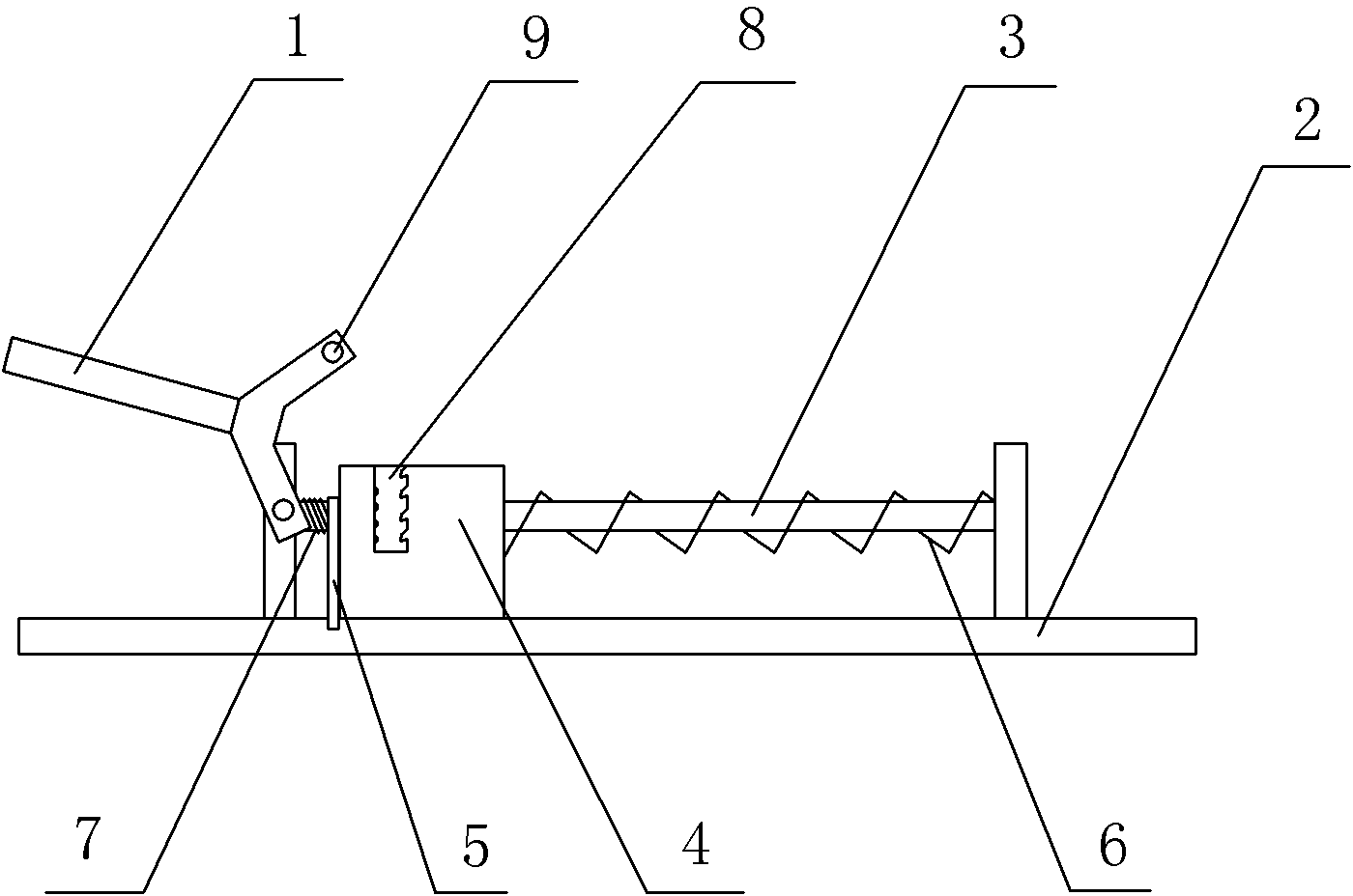
[0015] The reference signs in the drawings of the specification include: handle body 1, seat body 2, pole 3, locking block 4, limit block 5, first compression spring 6, second compression spring 7, bar-shaped hole 8, pin shaft 9.

[0016] Such as figure 1 As shown, a one-way positioning handle in this embodiment includes a seat body 2, a handle body 1, a support rod 3, a locking block 4, a limit block 5, and a first compression spring 6 sleeved on the support rod 3. And the second stage clip 7. Both ends of the strut 3 are detachably connected to the base body 2 . The right end of the limiting block 5 is movably connected on the base body 2, the locking block 4 is slidably connected on the pole 3, the right end of the first compression spring 6 is against the base body 2, the left end is against the right side of the locking block 4, and the locking block 4 The left side offsets with the limit block 5. The left end of the second compression spring 7 is against the seat bod...


PUM


Abstract

The invention discloses a unidirectional positioning handle which comprises a base, a handle body, a supporting rod, a locking block, a limiting block, a first compressed spring and a second compression spring. The first compressed spring and the second compression spring are connected with the supporting rod in a sleeving mode, the two ends of the supporting rod are fixed to the base, one end of the limiting block is movably connected with the base, the locking block is connected with the supporting rod in a sliding mode, one end of the compressed spring abuts against the base, the other end of the first compressed spring abuts against the front side of the locking block, the back side of the locking block abuts against the limiting block, one end of the second compressed spring abuts against the base, the other end of the second compressed spring abuts against the limiting block, one side of the handle body is hinged to the base, the other side of the handle body is provided with a pin shaft, the locking block is provided with a bar-shaped hole, the opening of the bar-shaped hole corresponds to the pin shaft in position, and the side, close to the front side of the locking block, of the inside of the bar-shaped hole is provided with a one-way gear. In a conventional state, the pin shaft abuts against the one-way gear in the bar-shaped hole. When the handle body needs to be reset reversely, a limiting plate can be removed, the pin shaft makes contact with the side, without the one-way gear, of the bar-shaped hole, and reversing reset is achieved.

Description

technical field [0001] The present invention belongs to the technical field of locking control members. Background technique [0002] The handle is a common mechanical control component, which is divided into a hand-held end and a control end. The hand-held end is used to input the action of the operation, and the control end will be connected to the corresponding mechanism to transmit the action input by the hand-held end to the corresponding mechanism. [0003] The existing handle usually does not have a special locking and positioning device, the handle cannot be positioned, and the control end of the handle is prone to instability. Especially when the handle controls the mechanism of one-way movement, the handle can be allowed to rotate in one direction, but not A mechanism that allows rotation in the other direction, without a corresponding positioning device, which cannot control the one-way movement well. Contents of the invention [0004] The invention provides a ...

Claims


Application Information

Patent Timeline
Patent Type & Authority Applications(China)
IPC IPC(8): G05G5/00
Inventor 马斌
Owner 重庆市南川区金鑫纸业有限公司
Why Eureka
Try Eureka