Fully automatic axle lathe jacking device

A technology of axle lathes and jacking devices, applied in metal processing, etc., can solve the problems of low adaptability, high production cost, short service life, etc., and achieve the effect of improved stability and high adaptability

Active Publication Date: 2017-05-10
利乐集美机械股份有限公司
View PDF5 Cites 0 Cited by
  • Summary
  • Abstract
  • Description
  • Claims
  • Application Information

AI Technical Summary

Problems solved by technology

[0004] The invention aims to solve the problems of the existing feeding mechanism for rod-shaped workpieces that the cylinder push rod is easy to bend and deform, has a short service life, high production cost, low stability of ejector pin and low adaptability

Method used


Image

  • Fully automatic axle lathe jacking device
  • Fully automatic axle lathe jacking device
  • Fully automatic axle lathe jacking device

Examples


Embodiment Construction

[0014] The present invention will be further described below in conjunction with the drawings and embodiments.

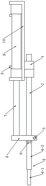
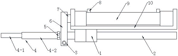
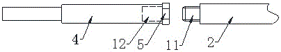
[0015] As shown in the figure, the present invention includes a cylinder 9 and a thimble 4. The cylinder 9 is fixed on the cylinder fixing seat 10, the left end of the cylinder 9 is provided with a cylinder push rod 7, and the cylinder fixing seat 10 is provided below There is a guide rod 2, a guide positioning sleeve 1 is sheathed on the outside of the guide rod 2, and the guide positioning sleeve 1 is fixed below the left end of the cylinder fixing seat 10; the left end of the cylinder push rod 7 and The left end of the guide rod 2 is connected and fixed by a synchronization fixing block 6. The left end of the guide rod 2 is provided with a screw head 11, the left side of the synchronization fixing block 6 is provided with a thimble 4, and the thimble 4 is fixed on the Screw head 11 on.

[0016] In this embodiment, the guide positioning sleeve 1 is sleeved on the righ...


PUM


Abstract

The invention discloses an ejecting device of a full-automatic axle lathe. The ejecting device comprises a cylinder and an ejector pin. The cylinder is fixed onto a cylinder fixing seat, a cylinder push rod is arranged at the left end of the cylinder, a guide rod is arranged below the cylinder fixing seat, and a guide positioning sleeve sleeves the guide rod and is fixed to the lower side of the left end of the cylinder fixing seat; the left end of the cylinder push rod is fixedly connected with the left end of the guide rod by a synchronous fixing block, a screw head is arranged at the left end of the guide rod, and the ejector pin is arranged on the left side of the synchronous fixing block and is fixed onto the screw head. The ejecting device has the advantages that the ejecting device is used for feeding rod-shaped workpieces into the full-automatic axle lathe, the ejector pin can be replaced according to the sizes of the workpieces, accordingly, the ejecting device is high in adaptability, and problems of high production cost and incapability of being used due to deformation of a cylinder push rod after an existing ejecting device is used for a long time can be solved.

Description

Technical field [0001] The invention relates to the field of equipment feeding devices, in particular to a fully automatic axle lathe feeding device. Background technique [0002] In the existing production equipment, feeding automation is very common. Automated production can not only increase the production speed, but also avoid work injuries caused by negligence in the manual feeding process, but nowadays there is no feeding mechanism for rod-shaped workpieces. The disadvantage is that the cylinder and the ejector pin are usually directly connected. This method makes the cylinder push rod easy to bend and deform, unusable, short service life, and high production cost. When the rod-shaped material is small in size, the ejector pin cannot be aligned. The materials are prone to skewed feeding, the stability is not high, and the size requirements for the materials that need to be ejected are high, and the adaptability is low. Summary of the invention [0003] The purpose of the pr...

Claims


Application Information

Patent Timeline
Patent Type & Authority Patents(China)
IPC IPC(8): B23B15/00
CPCB23Q7/006
Inventor 黄春平
Owner 利乐集美机械股份有限公司
Why Eureka
Try Eureka