
A track-type robot walking path changing device and its realization method

A transforming device and robot technology, applied in the directions of manipulators, manufacturing tools, etc., can solve the problems of failing to provide, restricting the application and promotion of orbital robots, and unable to expand the application of orbital robots, achieving a simple structure, conducive to maintenance and promotion, and improving The effect of job coverage

Active Publication Date: 2016-06-08
STATE GRID INTELLIGENCE TECH CO LTD
View PDF7 Cites 8 Cited by
  • Summary
  • Abstract
  • Description
  • Claims
  • Application Information

AI Technical Summary

Problems solved by technology

[0003] After searching the literature of the prior art, it was found that the patent with the application number 201310040511.1 titled "rail robot with turning device" and the patent with the title 201110091368.X titled "a track-type autonomous mobile robot" both proposed An application of orbital robots, but its research on the orbit of the robot is limited to the operation of a single orbit, and no specific and in-depth research and exploration have been carried out on the turning and bifurcation of the orbit, and it has not provided a The implementation plan is used to deal with the problem of multi-directional and multi-fork walking paths, which cannot expand the application of orbital robots
[0004] It can be seen that there is still no device in the current application technology to meet the needs of multi-directional and multi-branched orbital paths, and there are still relatively large technical defects in the application of orbital robots. This situation has seriously restricted the practical application of orbital robots and promotion

Method used


Image

  • A track-type robot walking path changing device and its realization method
  • A track-type robot walking path changing device and its realization method
  • A track-type robot walking path changing device and its realization method

Examples


Embodiment Construction

[0036] Below in conjunction with accompanying drawing and embodiment the present invention will be further described:

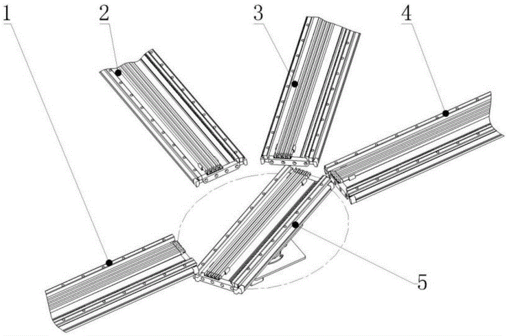
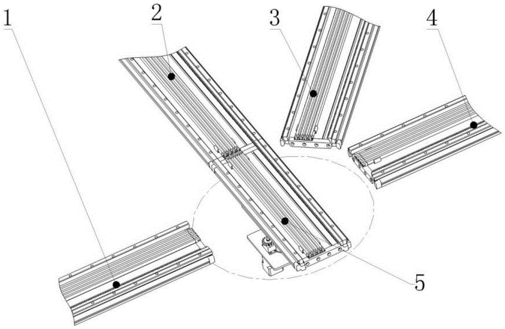
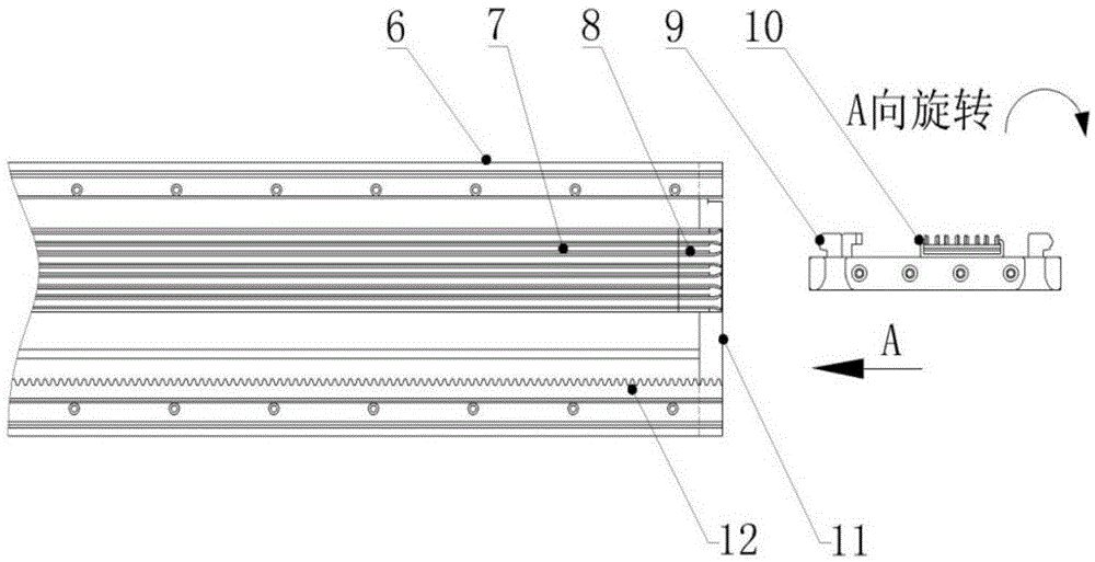
[0037] The embodiment of the present invention is mainly composed of a direction conversion platform, a first path track, a second path track, a third path track, a fourth path track or more path tracks, and the specific structure is as follows figure 1 with figure 2 shown. The length of the path track and the installation method with the building body are determined according to the actual situation on site.

[0038] The first path track 1 is erected on the support of the building body. According to the site requirements, there are multiple forks to adapt to different travel directions. In this case, three forks are used, and three travel directions can be selected, which are the second path track 2 and the second path. The three-path track 3 and the fourth-path track 4 are arranged with a direction switching platform 5 in the middle.

[0039] Such as ...


PUM


Abstract

The invention discloses a rail-mounted robot walking path changing device and an implement method thereof. The rail-mounted robot walking path changing device comprises a direction changing platform and a plurality of path rails different in the direction. The direction changing platform can be docked with any one of the path rails and comprises a platform base, a platform telescoping mechanism, a platform rotating mechanism and a platform mounting plate, wherein the platform base is connected with the platform telescoping mechanism, the platform telescoping mechanism is connected with the platform rotating mechanism, and the platform rotating mechanism is fixed on the platform mounting plate. The rail-mounted robot walking path changing device has the advantages that multi-channel coexistence and multi-direction selection are realized, one robot can complete jobs in many directions, and operation coverage rate is increased; the rail-mounted walking path changing device is high in applicability to path direction changes and applicable to various angle requirements, the defects of singularity in angle of turn of the curved rails and the paths are overcome, and design randomness of the paths is realized.

Description

technical field [0001] The invention belongs to the field of special robots, and in particular relates to a robot track application device for changing the walking path of a robot by changing the direction of the track. Background technique [0002] In the application of equipment inspection and material transfer, orbital robots have been gradually applied due to their advantages of strong battery life and convenient maintenance. In order to increase the geographical scope of the robot’s operation and improve the coverage of equipment testing and material delivery locations, it is necessary to extend the robot’s track to many corners, which involves turning and bifurcation of the track path. Some paths have too large turning angles, There are too many forks, and the ordinary curved rail design can no longer solve it, which brings many technical difficulties to the walking of the orbital robot. Therefore, the research on a device that can change the walking path of the robot...

Claims


Application Information

Patent Timeline
Patent Type & Authority Patents(China)
IPC IPC(8): B25J19/00B25J5/02
Inventor 李运厂刘永成蒋克强孟杰孙昊隋吉超张永生
Owner STATE GRID INTELLIGENCE TECH CO LTD
Learn More