Self-balancing wheelbarrow with pedals provided with auxiliary wheels

A technology for unicycles and auxiliary wheels, which is applied to unicycles, bicycles, pedals, etc., and can solve problems such as bruises, inapplicability, discomfort between the calf and the side wall, etc., and achieve the effect of smooth parking

Inactive Publication Date: 2015-01-28
赵俊春
View PDF5 Cites 2 Cited by
  • Summary
  • Abstract
  • Description
  • Claims
  • Application Information

AI Technical Summary

Problems solved by technology

The rise of self-balancing electric unicycles is about to trigger a new traffic revolution; when riding an existing electric unicycle, it is necessary to step on the pedal with one foot first, and the calf and the side wall are offset to form a stable triangular structure. Then stand on the other leg to realize the riding action; but the calf and the side wall are very uncomfortable, and it will cause bruises after riding for a long time
Existing unicycles are generally equipped with auxiliary wheels that can be detachably connected to the pedals. However, this type of auxiliary wheel can only be used for users to find a sense of balance when they are beginners, and it is not suitable for normal riding.

Method used


Image

  • Self-balancing wheelbarrow with pedals provided with auxiliary wheels
  • Self-balancing wheelbarrow with pedals provided with auxiliary wheels
  • Self-balancing wheelbarrow with pedals provided with auxiliary wheels

Examples


Embodiment 1

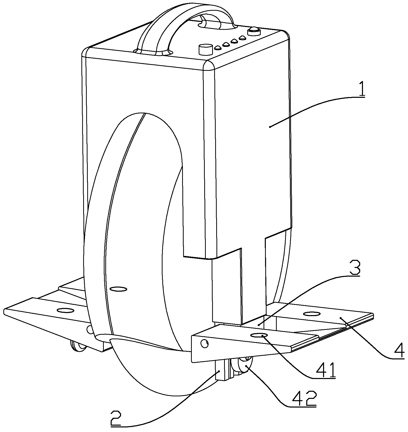
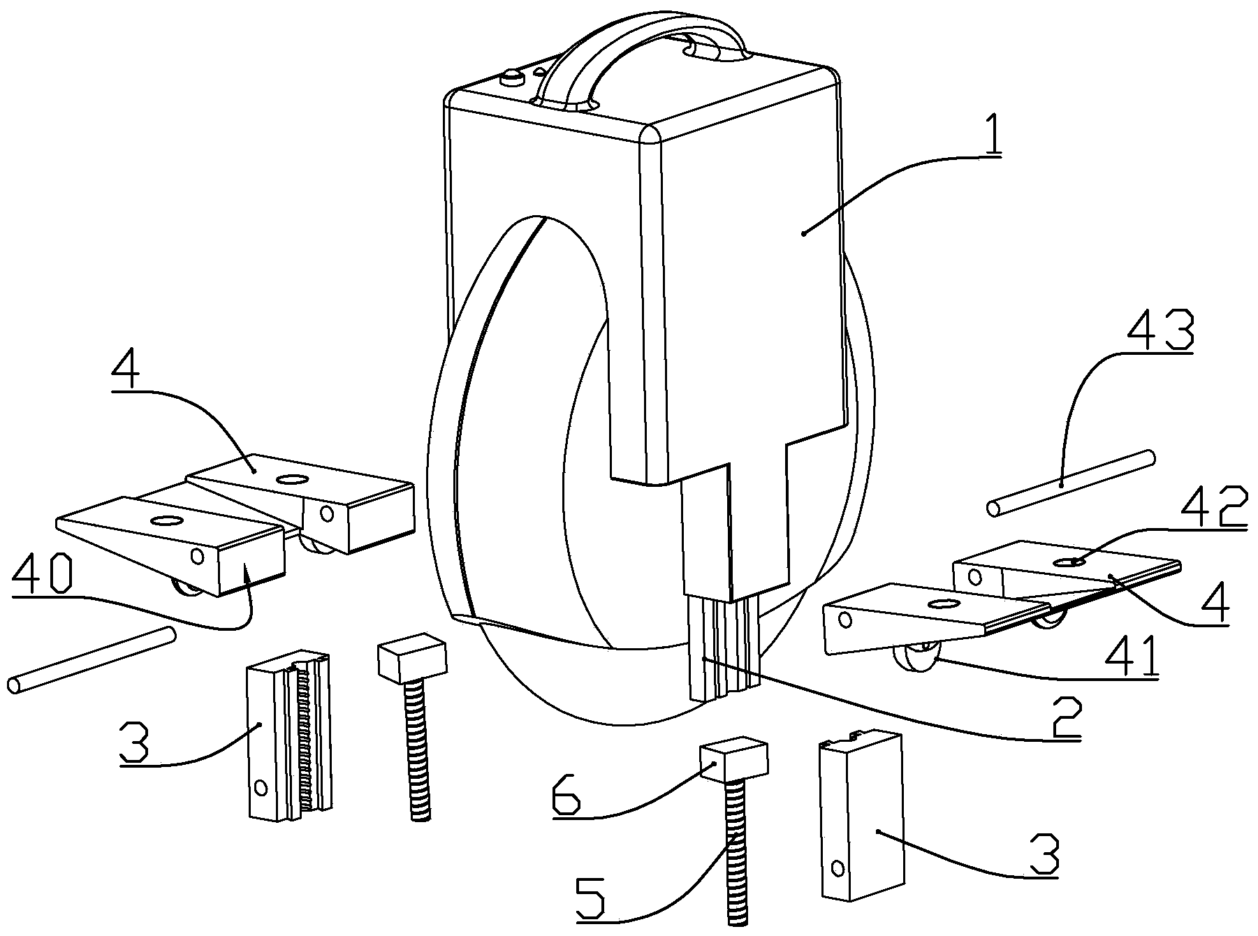
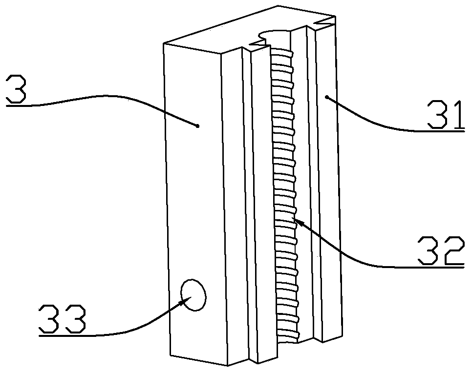
[0014] according to Figure 1 to Figure 4 As shown, a self-balancing unicycle with auxiliary wheels on the pedals described in this embodiment includes a vehicle body 1, two vertically arranged pedal mounting rods 2 fixedly installed on both sides of the vehicle body, and The two pedals 4; the upper end of the pedal installation rod is fixedly connected with the central axis of the unicycle motor, the auxiliary wheel 41 is installed below the pedal, and the two pedal installation rods are slidably connected with a sliding block 3 in the vertical direction, so The pedal is rotatably connected to the sliding block through the connecting shaft 43; the upper part of the pedal mounting rod 2 is connected with a transmission screw 5 through a bearing, and the transmission screw is in transmission connection with a drive module 6 installed in the vehicle body, and the sliding block is installed toward the pedal. One side of the rod is formed with a transmission thread 32 that is conn...

Embodiment 2

[0022] A self-balancing unicycle with auxiliary wheels on the pedals described in this embodiment includes a vehicle body 1, two vertically arranged pedal mounting rods 2 fixedly installed on both sides of the vehicle body, and two Pedal 4; the upper end of the pedal mounting rod is fixedly connected with the central axis of the unicycle motor, and the auxiliary wheel 41 is installed below the pedal, and the two pedal mounting rods are slidably connected with a sliding block 3 in the vertical direction, and the pedal passes through The connecting shaft 43 is rotatably connected to the sliding block; the upper part of the pedal installation rod 2 is connected with a transmission screw 5 through a bearing, and the transmission screw is in transmission connection with a drive module 6 installed in the vehicle body, and the sliding block faces one side of the pedal installation rod The transmission thread 32 is formed to cooperate with the transmission screw; the drive module is el...

Embodiment 3

[0027]A self-balancing unicycle with auxiliary wheels on the pedals described in this embodiment includes a vehicle body 1, two vertically arranged pedal mounting rods 2 fixedly installed on both sides of the vehicle body, and two Pedal 4; the upper end of the pedal mounting rod is fixedly connected with the central axis of the unicycle motor, and the auxiliary wheel 41 is installed below the pedal, and the two pedal mounting rods are slidably connected with a sliding block 3 in the vertical direction, and the pedal passes through The connecting shaft 43 is rotatably connected to the sliding block; the upper part of the pedal installation rod 2 is connected with a transmission screw 5 through a bearing, and the transmission screw is in transmission connection with a drive module 6 installed in the vehicle body, and the sliding block faces one side of the pedal installation rod A transmission thread 32 is formed to cooperate with the transmission screw for transmission connectio...


PUM


Abstract

The invention discloses a self-balancing wheelbarrow with pedals provided with auxiliary wheels. The self-balancing wheelbarrow comprises a wheelbarrow body, two vertical pedal installation rods arranged on two sides of the wheelbarrow body, and two pedals arranged on two sides of the wheelbarrow body. The auxiliary wheels are installed below the pedals, the two pedal installation rods are slidably connected with sliders in the vertical direction, and the pedals are rotatably connected onto the sliders through connection shafts. The upper portions of the pedal installation rods are connected with drive screws through bearings, and the drive screws are in transmission connection with a driving module installed in the wheelbarrow body. Transmission threads in transmission connection with the drive screws in a matched way are formed on the surfaces of the sliders facing the pedal installation rods. Sensors used for detecting whether feet of a user stamp on the pedals are installed above the two pedals respectively, and the sensors and the driving module are electrically connected with a controller. The pedal system makes getting on and off the wheelbarrow to be very easy, thereby enabling more people to learn to ride the wheelbarrow easily.

Description

technical field [0001] The invention belongs to the field of unicycle structure, and in particular relates to a unicycle with auxiliary wheels. Background technique [0002] Self-balancing electric unicycle is a means of transportation with electric drive and self-balancing function. With the rapid development of society today, traffic congestion has become a common phenomenon. Electric unicycles replace bicycles and electric vehicles as transportation tools. The rise of self-balancing electric unicycles is about to trigger a new traffic revolution; when riding an existing electric unicycle, it is necessary to step on the pedal with one foot first, and the calf and the side wall are offset to form a stable triangular structure. Then stand on the other leg to realize the riding action; but the calf and the side wall are very uncomfortable, and it will cause bruises after riding for a long time. Existing unicycles are generally equipped with auxiliary wheels that can be d...

Claims


Application Information

Patent Timeline
Patent Type & Authority Applications(China)
IPC IPC(8): B62K11/00B62M6/45B62M6/50
CPCB62J25/00B62K1/00B62K11/00
Inventor 李陈
Owner 赵俊春
Why Eureka
Try Eureka