Solar panel mounting frame with front and back limiting function

A solar panel and mounting frame technology, which is applied to electrical components, photovoltaic power generation, photovoltaic module support structures, etc., can solve the problems of large volume of solar panels and heavy workload, etc.

Inactive Publication Date: 2015-02-04
国网山东莱州市供电公司 +1
View PDF9 Cites 9 Cited by
  • Summary
  • Abstract
  • Description
  • Claims
  • Application Information

AI Technical Summary

Problems solved by technology

Due to the huge volume of solar panels, when a solar pane

Method used


Image

  • Solar panel mounting frame with front and back limiting function
  • Solar panel mounting frame with front and back limiting function
  • Solar panel mounting frame with front and back limiting function

Examples


Embodiment Construction

[0018] combined with Figure 1-5 , the present invention is explained in detail.

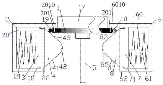
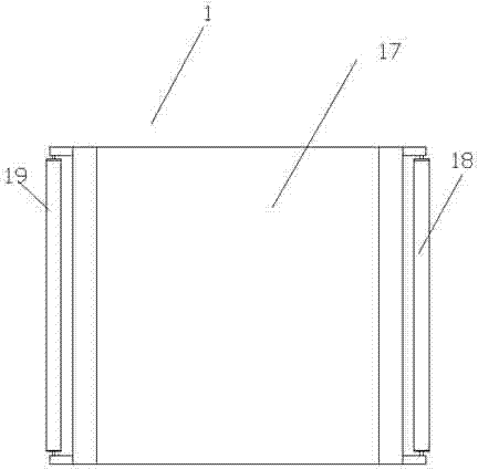
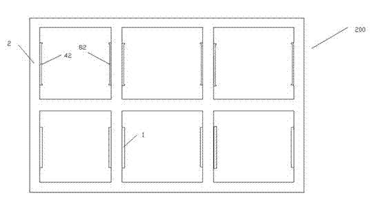
[0019] A solar cell panel mounting frame with front and rear limit function includes a frame assembly 200 and a plurality of mounting plates 1, each of which is used for installing the solar cell panel 17, and the frame assembly 200 has a plurality of mounting plates 1. a plurality of installation windows, each of which is used to carry the one of the installation panels 1 so that the solar cell panel can be in a working state of receiving sunlight;

[0020] Each of the installation windows includes a left frame 2, a right frame 6, and a window area 26 between the left frame 2 and the right frame 6, and the window area 26 is used to expose the solar cell panel to receive sunlight;

[0021] The left frame 2 has a left cavity 20, and a left slider 3 is slidably arranged in the left cavity 20. The left side of the left slider 3 is engaged with the right end of the left top pressure spring 21, and...


PUM


Abstract

Disclosed is a solar panel mounting frame with a front and back limiting function. The mounting frame comprises a frame assembly (200) and multiple mounting plates (1), the multiple mounting plates (1) are each used for mounting a solar panel (17), the frame assembly (200) is provided with multiple mounting empty windows, and each mounting empty window is used for bearing one mounting plate (1) so as to enable the solar panel to be at a working state of receiving sunlight.

Description

technical field [0001] The invention relates to an installation of a solar cell panel, in particular to an installation of a solar cell panel that is easy to disassemble. Background technique [0002] In a solar panel power plant, a large number of solar panels need to be installed. Due to the huge volume of solar panels, when the solar panels fail or require maintenance, their workload is often large. [0003] Automation and mechanization of solar panel disassembly can solve this problem. However, through automated and mechanized quick loading and unloading of solar panels, there is a need for a mounting frame for solar panels that facilitates quick loading and unloading. SUMMARY OF THE INVENTION [0004] The present invention aims to provide an installation method of a solar cell panel, which can be disassembled and installed quickly, and is convenient to realize the automation of disassembly and assembly. [0005] According to an aspect of the present invention, a so...

Claims


Application Information

Patent Timeline
IPC IPC(8): H02S30/10H02S20/30
CPCH02S20/00H02S30/00Y02E10/50
Inventor 舒泳军
Owner 国网山东莱州市供电公司
Why Eureka
Try Eureka