Vibration dampers, especially piston rod dampers for motor vehicles

A technology of piston rod and shock absorber, applied in the direction of shock absorber, spring/shock absorber, shock absorber, etc., can solve the problems of vibration shock absorber damage, end stop 23 disengagement, etc. Stable force and reliable locking effect

Active Publication Date: 2016-05-04
SCHAEFFLER TECH AG & CO KG
View PDF6 Cites 0 Cited by
  • Summary
  • Abstract
  • Description
  • Claims
  • Application Information

AI Technical Summary

Problems solved by technology

If an extremely high force is exerted on the axial end stop 23, the end stop 23 will disengage, which causes damage to the vibration damper 17

Method used


Image

  • Vibration dampers, especially piston rod dampers for motor vehicles
  • Vibration dampers, especially piston rod dampers for motor vehicles
  • Vibration dampers, especially piston rod dampers for motor vehicles

Examples


Embodiment Construction

[0020] Like features are provided with like reference numerals.

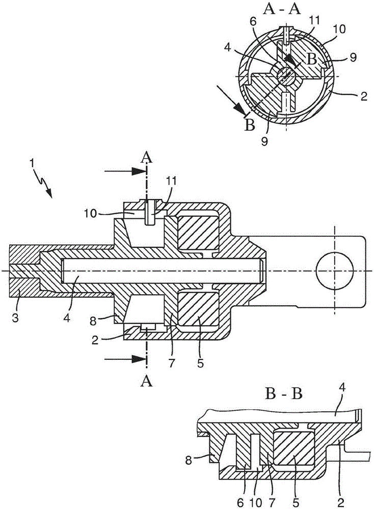
[0021] exist figure 1 shows a piston rod damper 1 which is designed to connect a clutch pedal to a master cylinder of a clutch operating system in a motor vehicle. The piston rod damper 1 is formed by a damper housing 2 into which a piston rod 3 is introduced. The damper housing 2 is connected here to a clutch pedal, not shown further, while the piston rod 3 is guided on a master cylinder, likewise not shown, of the clutch operating system of the motor vehicle,

[0022] The piston rod 3 surrounds a cylindrical pin 4 which protrudes beyond the piston rod 3 in the direction of the damper housing 2 . In this case, the end of the pin 4 engages in the damping housing 2 , wherein the pin 4 is fixedly seated in the piston rod 3 , while the pin 4 is held in a floating bearing in the damping housing 2 . A damping element in the form of a rubber damper 5 is arranged within the damping housing 2 between the damping hou...


PUM


Abstract

A vibration damper, in particular a piston-rod damper for a motor vehicle, comprising a damping housing (2) which receives a piston rod (3), the piston rod comprising a pin (4) which is mounted with play in the damping housing (2), wherein a first plate (6) of the piston rod (3) is locked to the damping housing (2), and a damping element (5) is mounted between the piston rod (3) and the damping housing (2), wherein the locking between the first plate (6) of the piston rod (3) and the damping housing (2) is realized in the form of a bayonet-like lock (9, 10).

Description

technical field [0001] The invention relates to a vibration damper, in particular a piston rod damper for a motor vehicle, comprising a damper housing which accommodates a piston rod which encloses a pin with A certain gap is accommodated in the damping housing, wherein the first disc of the piston rod is locked with the damping housing, and a damping element is arranged between the piston rod and the damping housing. Background technique [0002] In motor vehicles, vibration dampers are used in the connection between a hydraulic clutch master cylinder of a clutch operating device and a clutch pedal. Figure 6 A vibration damper 17 consisting of a damping housing 18 and a piston rod 19 is shown. The piston rod 19 extends here rotationally symmetrically about a pin 20 which is immovably arranged in the piston rod 19 in a fixed bearing P. As shown in FIG. The pin 20 protrudes beyond the piston rod 19 and engages with its free end into the damping housing 18 , where it is seat...

Claims


Application Information

Patent Timeline
Patent Type & Authority Patents(China)
IPC IPC(8): F16F1/371F16F1/44F16F7/108F16F9/092
CPCF16F1/371F16F1/3814F16F1/445
Inventor 马库斯·海特鲍姆弗兰克·弗里奇
Owner SCHAEFFLER TECH AG & CO KG
Why Eureka
Try Eureka