[0036] When the thermostat of the present invention is specifically used, the heat-sensitive substance of the thermodynamic element expands or contracts according to the oil temperature in the thermostat, thereby controlling the flow rate of the lubricating oil into the external fluid cooling device, and the The working temperature of the lubricating oil is controlled within the effective range, and the temperature of the lubricating oil is not allowed to be too high or too low, so that the lubrication of the lubricating oil is better, thereby effectively protecting the gearbox; and the push rod of the thermal element has a limit In this way, the movable stroke of the push rod can be ensured, and the rubber tube of the thermal element will not be damaged due to the excessive stroke, and even if the initial position is incorrect, the push rod will not interfere with the bottom of the hose, thus ensuring the product Life. The specific implementation of the thermostat of the present invention will be described in detail below with reference to the accompanying drawings:
[0037] The orientation nouns such as top, bottom, left, right, up, and down described in this manual are all described in accordance with the relationship between up and down, left and right in the drawings; in addition, some sorts such as first, second, etc. are mainly for clarity of explanation. The distinction should not be regarded as a limitation of the present invention. The initial deformation force of the second elastic element 42 mentioned in this specification means that when the second elastic element 42 is compressed and deformed by the pressure of the push rod, the stopper for limiting the push rod just no longer bears the second elastic element. The pressure applied by the two elastic elements 42 is the pressure or the elastic force of the second elastic element 42.
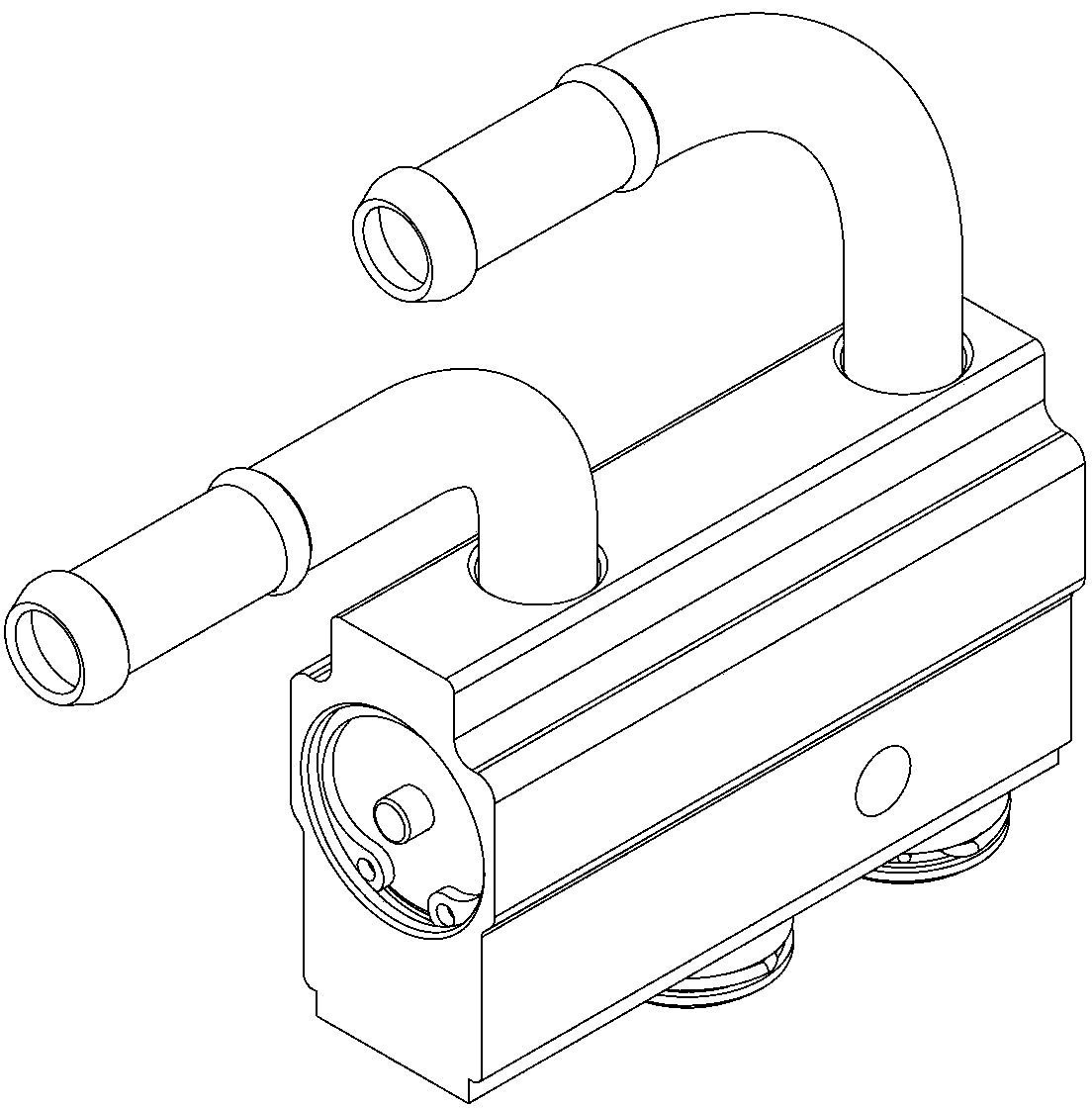
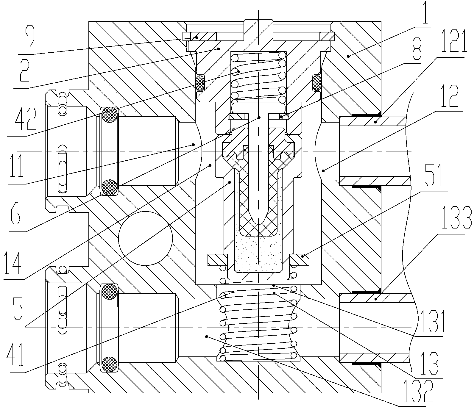
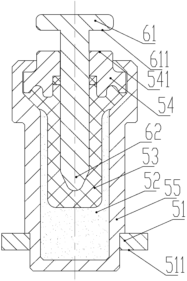
[0038] Figure 1 to Figure 3 It is the first embodiment of the thermostat of the present invention. The thermostat includes a valve body 1 provided with a containing cavity 14 and a thermodynamic element fitted in the containing cavity 14; The push rod 6 at one end of the body part, one end of the push rod 6 is exposed outside the body part 5; the valve body 1 is provided with an open end, the open end is closed by an end cover 2, and the end cover 2 is fixed to the valve under the action of a circlip 9. The open end of the body 1; the thermodynamic element is installed in the accommodating cavity 14 of the valve body 1 through two elastic elements (first elastic element, second elastic element). The valve body 1 also includes three ports: a first port 11, a second port 12, and a third port 13. A valve port 131 is provided between the third port 13 and the first port 11 and the second port 12. The first port 11 The connection with the second interface 12 is conducted through the containing cavity 14. The body part 5 of the thermodynamic element includes a body 55, an abutment part 51 integrally provided or fixed with the body 55, a heat-sensitive material 52 and a rubber tube 53 located in the cavity of the body 55, and a heat-sensitive material 52, a rubber tube 53 Seal the packaged head 54. When the thermodynamic element is heated, the heat-sensitive material 52 expands and pushes the rubber tube 53 to compress and squeeze upward, thereby causing the push rod to move relative to the main body. After the push rod 6 or indirectly abuts against the second elastic element 42, the main body 5 Moving relative to the push rod 6 means moving in the direction of the third interface 13, until the abutment portion 51 of the body abuts against the bottom wall surface of the valve port 131, that is, the valve body is on the bottom wall of the plane where the valve port 131 is located. The two elastic elements 42 move in the direction of the end cap. The second elastic element is arranged on the end cover or on the side close to the end cover, one end of the second elastic element abuts against the end cover, and the other end at least collides or indirectly collides with the push rod when in motion; the first elastic element 41 Set at the third interface or on the side close to the third interface, one end of the first elastic element 41 abuts on the inner wall or bottom wall of the valve body accommodating cavity, and the other end abuts on the main body 5; The initial deformation force of the element 42 is greater than or equal to the pressure that the first elastic element 41 receives when the body part covers the first valve port.
[0039] Specifically, in this embodiment, the open end of the valve body 1 is provided with a circlip 9, and the end cap 2 is fixed to the open end of the valve body 1 under the action of the circlip 9, and its radial position is the same as the open end of the valve body 1. Cooperating and fixing, the end cap 2 is in tight contact with the circlip 9 to fix its axial position. In order to ensure sealing, a sealing ring is provided between the end cover 2 and the inner wall of the valve body 1. The end cover 2 is provided with a accommodating cavity, and the second elastic element 42 is arranged in the accommodating cavity of the end cover. One end of the second elastic element 42 abuts against the bottom wall of the end cover accommodating cavity, and the other end is in contact with the limiting portion of the push rod 6 61 abuts; the second elastic element 42 and the limiting portion 61 of the push rod 6 are limited in the receiving cavity of the end cover by the retaining member 8. The push rod 6 has a substantially "T"-shaped structure, and the large diameter end of the push rod 6 forms its limiting part; the limiting part 61 of the push rod 6 is larger than the inner hole of the retaining member 8, and the small diameter end of the push rod 6 is smaller than The inner hole portion of the retaining member 8 is disposed through the retaining member 8, and the inner end 62 of the small diameter end of the push rod 6 extends into the hole of the body portion 5 of the thermal element. One end of the first elastic element 41 abuts on the bottom wall of the third interface 13, and the other end abuts on the abutment 51 of the main body 5.
[0040] In addition, for the convenience of connection, the thermostat also has four connection ports, which are two external ports provided on the outer side of the valve body 1, and a connecting pipe provided on the other side of the valve body 1: the first connecting pipe 121 and The second connection tube 133. Wherein, the first connecting pipe 121 communicates with the second interface 12, and the second connecting pipe 133 communicates with the third interface 13 through the third flow channel 132. When the temperature of the fluid is low, the heat-sensitive material in the thermodynamic element shrinks, and the elastic force of the first elastic element 41 urges the thermodynamic element body 5 to move toward the end cover until the upper end surface of the body 55 of the thermodynamic element body is sealed. The upper end surface 541 of the head 54 abuts against the end cap or the clamping member; at this time, the third port 13 is in communication with the first port 11 and the second port 12, and the fluid coming in from the first port or the second port is directly from the valve port 131. The third port 13 flows out; in addition, the fluid flow direction can also be reversed, that is, it enters from the third channel connected with the third port and flows out from the first port or the second port. The lower fluid temperature means that the temperature reaches the preset low temperature and below. When the fluid temperature is lower, even if the heat-sensitive material shrinks further, since the limiting surface 611 of the limiting portion 61 of the push rod 6 is resisted by the retaining member 8, the pushing rod will not further extend into the hole of the body part. It can effectively protect the hose 53 in the body, thereby ensuring the service life of the product. When the fluid temperature is high, the heat-sensitive material in the thermodynamic element expands. After the push rod 6 collides or indirectly hits the second elastic element 42, the main body 5 moves relative to the push rod 6, that is, moves toward the third interface 13 , Until the abutting portion 51 provided on the main body 5 abuts against the position where the valve port 131 is located to seal the third interface 13, at this time, the abutting surface 511 of the abutting portion 51 abuts the flat portion of the position where the valve port 131 is located, The third interface no longer communicates with the first interface 11 and the second interface 12; and when the temperature of the fluid further rises, the push rod 6 overcomes the elastic force of the second elastic element 42 to move relative to the body portion 5. Higher fluid temperature means that the temperature reaches the preset high temperature and above. In this way, the thermostat controls the flow rate through the third interface through the movement of the thermal element body relative to the push rod, which can effectively control the fluid temperature of the thermostat.
[0041] When assembling, first install the body of the first elastic element and the thermal element into the valve body; and assemble the push rod of the thermal element and the second elastic element with the end cap through the clamping piece to form an assembly; Then put the assembly into the valve body, align the inner end of the push rod with the inner hole of the body, and finally use the circlip to limit the end cover to the open end of the valve body.
[0042] The second embodiment of the present invention is described below, such as Figure 4 , Figure 5 As shown, the main difference between this embodiment and the first embodiment described above lies in the structure of the end cap, the positioning mode of the second elastic element, and the limiting mode of the push rod. In this embodiment, the end cap 2 is not provided with a accommodating cavity, and a retaining ring 80 is fixedly provided inside the open end of the valve body. The retaining ring 80 can be tightly fitted with the open end of the valve body, or it can also be clamped The way is fixed; the retaining ring 80 serves as a stop for the push rod to move to the inside of the body, and at the same time as a stop for the body of the thermal element to move to the end cover; in addition, the end cover 2 is provided with a convex inward Out portion 21, and the push rod is provided with a recessed positioning portion 612 at its limiting portion facing the end cover. One end of the second elastic element 42 abuts on the end face of the end cover facing inward, and the other end abuts on the positioning of the push rod. The bottom surface of the portion 612, the radial direction of the second elastic element 42 is received by the positioning portion 612 of the push rod and the protruding portion 21 of the end cap to obtain better positioning. The advantage of this embodiment is that the assembly is relatively simple. Similarly, the push rod will not extend too deep into the body of the thermodynamic element due to being blocked by the retaining ring at low temperatures. In addition, the fixing method of the end cap and the valve body is not limited to the circlip fixing method described above, and other fixing methods such as threaded connection may also be used.
[0043] The third embodiment of the present invention is described below, such as Image 6 , Figure 7 As shown, the main difference between this embodiment and the first embodiment described above is the difference in the setting part of the limiting structure. In this embodiment, the push rod 6a also has a large diameter portion as the limiting portion 63, and the limiting portion 63 passes The spring seat 7 conflicts with the second elastic element 42, specifically the upper plane 631 of the limiting portion 63 conflicts with the bottom surface of the spring seat 7, and the other surface of the spring seat 7 conflicts with the second elastic element 42; The rod can be assembled with the body part 5 first, and the installation is relatively convenient; in addition, the limiting structure is provided on the limiting surface 632 of the limiting portion 63 of the push rod 6a and the upper end surface of the head 54, that is, through the pushing rod 6a The limit surface 632 of the end contact with the upper end surface 541 of the head 54 realizes the limit of the push rod; other structures of this embodiment can refer to the first embodiment, and will not be repeated here.
[0044] The fourth embodiment of the present invention is described below, such as Picture 8 , Picture 9 As shown, the main difference between this embodiment and the third embodiment described above is the difference in the structure of the spring seat. In this embodiment, the structure of the spring seat 7a is similar to a straw hat, while the spring seat 7 in the third embodiment is roughly flat. shape. In this way, the limiting portion 63 of the push rod 6a can extend into the straw hat-shaped inner cavity of the spring seat 7a, so that the radial position of the push rod can be better positioned; in addition, because the straw hat shape of the spring seat 7a is facing the first The two elastic elements protrude in the direction, which also enables the second elastic element 42 to obtain a good positioning, which makes the action of the thermostat more reliable. In addition, the limit parts of the push rod in the several embodiments described above are generally stepped cylindrical. The present invention is not limited to this. The limit part may also be a protrusion that protrudes from the base of the push rod, such as Two or more radially convex ear structures or ring structures, etc., can also achieve the purpose of limiting, such as Picture 10 Shown.
[0045] In specific use, the thermostat connects to the external cooling device and the transmission oil tank through the pipeline. The temperature change of the incoming fluid controls the flow of the fluid entering the external external cooling device, thereby ensuring the temperature of the fluid returning to the gearbox oil tank.
[0046] In the several embodiments described above, the first interface and the second interface are directly connected. The present invention is not limited to this. A second valve port can also be provided between the first interface and the second interface, such as Picture 11 , 12 Shown. Picture 11 This is a schematic cross-sectional view of the fifth embodiment of the thermostat of the present invention. The main difference between this embodiment and the second embodiment described above is that the second interface is set at a different position, and there is also a difference between the first interface and the second interface. A second valve port is provided. Specifically, the second interface 120 is located near the end cap 2. A retaining member 8a is also fixedly provided in the accommodating cavity 14 of the valve body 1. The retaining member 8a has a through hole portion which is biased toward the heat There is a second valve port 81 on one side of the main body of the moving element; the limiting portion 61 of the push rod 60 is larger than the through hole portion of the retaining member 8a, and the limiting portion 61 is located on the other side of the retaining member 8a, which is close to the end cover. One side; one end of the second elastic element 42 abuts against the bottom surface of the end cap 2, and the other end abuts against the bottom of the recessed portion 61, and the radial positioning is achieved by the recessed positioning portion; in addition, in order to make the second elastic The element 42 is positioned accurately, and a protrusion 21 is also provided on the end cover; on the one hand, the retaining member 8a serves as a limiting structure for the push rod 60, so that the push rod will not extend too far into the direction of the body 5 of the thermal element In addition, the retaining member 8a is also provided with a valve port as the communication between the second interface 120 and the first interface 11, which is opened or closed in cooperation with the second abutment portion provided or fixed on the body portion 5 of the thermal element, And when the second valve port is opened, it is conducted through the circulation channel provided on the limiting portion, and the circulation channel may specifically be a through hole portion provided on the limiting portion or a notch on the limiting portion; in this embodiment, the second The abutment part is the mating part 551 of the main body part 5 of the thermodynamic element that is biased toward the end cap side. When the fluid temperature is low, the thermosensitive material 52 shrinks, and the elastic force of the first elastic element 41 promotes the main body part of the thermodynamic element. Moving toward the end cap, the body portion 5 of the thermal element moves relative to the push rod 60, that is, to the end cap side, until the mating portion 551 of the body portion 5 of the thermal element abuts the second valve port 81, and then the first The interface 11 and the second interface 120 are no longer connected; when the temperature of the fluid is high, the heat-sensitive material 52 expands, and the body portion 5 of the thermodynamic element overcomes the elastic force of the first elastic element 41 and moves away from the end cap when it moves relative to the push rod. Move in the direction, the first interface 11 and the second interface 120 are connected through the circulation channel provided on the limit part, and the fluid can enter from the first interface through the second interface or flow from the second interface through the first interface; if The temperature of the fluid continues to rise, and the body portion 5 of the thermal element continues to move relative to the push rod 60, that is, to the side away from the end cap, until the abutment portion 51 of the body portion 5 of the thermal element abuts the valve port 131, so that the third The circulation of the interface 13 is blocked, and the first interface 11 and the second interface 120 are completely connected. In this way, the flow rate of the fluid when there is no need to communicate between the first interface and the second interface can be reduced, and the flow control of the fluid can be more accurate.
[0047] In the several embodiments described above, the end cover 2 and the valve body 1 are all fixed by a circlip 9, that is, the end cover 2 is fixed to the open end of the valve body 1 under the action of the circlip 9. The present invention does not Not limited to this, a threaded part can also be set between the end cover and the valve body for fixing, such as Figure 12-15 As shown, this is a schematic cross-sectional view of the sixth embodiment of the thermoregulator of the present invention. The main difference between this embodiment and the fifth embodiment is the fixing method of the end cover and the valve body, and the structure of the push rod. The end cap 2 of this embodiment is provided with an external thread 22, and the valve body 1 is provided with an internal thread 15 at its open end, so that the two are fixed together and sealed by a seal; this is relatively convenient for use and maintenance. In addition, the push rod 6b of this embodiment also includes a stop part 63 that cooperates with the stop part 8a to control the depth of the push rod into the body part, specifically through the stop surface 633 of the stop part 63 and the stop part 8a. The upper plane conflicts to achieve the limit. In addition, the push rod 6b in this embodiment also has a concave positioning portion 634 for positioning the second elastic element 42, and a through hole portion 635 is also provided. Specifically, the through hole portion may be such as Figure 14 As shown in the circular hole, the number of the through hole portion can be 1-6; in addition, the through hole portion 635 can also be as Figure 16 The arc-shaped combined structure shown can reduce the weight of the push rod, and in addition, can be used as the limiting portion of the circulation channel to conduct fluid circulation. The push rod can be an integral structure made by machining, or an integral structure made by injection molding; it can also be a structure fixed together by assembly, for example, the limit part can be fixedly connected with The small diameter part of the push rod is fixed to form the push rod, and the specific fixed connection method is threaded connection, welding fixation, or tight fitting fixation.