An organic electroluminescent device

An electroluminescent device and electroluminescent technology, which are applied to static indicators, instruments, etc., can solve the problems of waste of resources, failure of normal display body, and abandonment, and achieve the effects of saving resources, reducing the width of the frame, and enhancing the driving ability.

Active Publication Date: 2017-10-10
KUNSHAN GO VISIONOX OPTO ELECTRONICS CO LTD
View PDF5 Cites 0 Cited by
  • Summary
  • Abstract
  • Description
  • Claims
  • Application Information

AI Technical Summary

Problems solved by technology

[0006] For this reason, what the present invention aims to solve is that the existing organic electroluminescent device for display can be lighted up but cannot be displayed normally due to manufacturing defects, thereby causing the screen body to be discarded, thereby causing waste of resources. Organic electroluminescent device with mode switching at any time

Method used


Image

  • An organic electroluminescent device
  • An organic electroluminescent device
  • An organic electroluminescent device

Examples


Embodiment 1

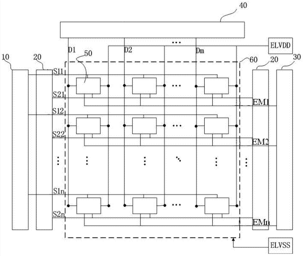
[0034] This embodiment provides an organic electroluminescent device, such as figure 2 As shown, it includes a data driver 40, a first scan driver 10, two second scan drivers 20, a third scan driver 30, several pixel units 50 arranged in an array, and a first power supply ELVDD, a second power supply ELVSS .

[0035] The first scan driver 10 and the third scan driver 30 are respectively arranged on both sides of the array 60 formed by the pixel units 50; the two second scan drivers 20 are respectively connected to the first scan driver 10, the The third scan driver 30 is disposed on the same side of the array formed by the pixel units 50 .

[0036] The organic electroluminescent device is provided with two second scanning drivers 20, which effectively enhances its driving capability, and has smaller rising and falling edges than independent scanning drivers, so the second scanning driver 20 can enhance its driving ability as a double-terminal driver. Drive capability. As a...

Embodiment 2

[0047] This embodiment provides an organic electroluminescent device, such as figure 2 As shown, it includes a data driver 40, a first scan driver 10, two second scan drivers 20, a third scan driver 30, several pixel units 50 arranged in an array, and a first power supply ELVDD, a second power supply ELVSS .

[0048] The first scan driver 10 and the third scan driver 30 are respectively arranged on both sides of the array 60 formed by the pixel units 50; the two second scan drivers 20 are respectively connected to the first scan driver 10, the The third scan driver 30 is disposed on the same side of the array formed by the pixel units 50 .

[0049] The organic electroluminescent device is provided with two second scanning drivers 20, which effectively enhances its driving capability, and has smaller rising and falling edges than independent scanning drivers, so the second scanning driver 20 can enhance its driving ability as a double-terminal driver. Drive capability. As a...


PUM


Abstract

The invention belongs to the field of organic electroluminescence. The organic electroluminescence device includes a data driver, a first scan driver, two second scan drivers, a third scan driver, and a plurality of pixels arranged in an array unit; each column of pixel units is connected in series to the data driver through the data line; each row of pixel units is connected in series to the first scan driver through the first scan line; each row of pixel units is connected in series to the second scan driver through the second scan line Driver; the pixel units in each row are connected in series and connected to the third scanning driver through the third scanning line; each scanning line is electrically connected to a mode conversion unit for adjusting the level of each scanning line, thereby realizing an organic electroluminescent device The display mode and lighting mode can be switched arbitrarily, so as to realize the reuse of bad screens that can be lit but cannot be displayed normally, effectively saving resources.

Description

technical field [0001] The invention relates to the field of display technology, in particular to an organic electroluminescence device which can be switched between a display mode and an illumination mode at will. Background technique [0002] Flat panel display has the characteristics of complete planarization, lightness, thinness, and power saving. It is an inevitable trend and research focus of image display development. In various types of flat panel display devices, since the active matrix organic electroluminescent device (English full name is Active Matrix Organic Light Emitting Display, referred to as AMOLED) uses self-luminous organic light emitting diode (English full name is Organic Light Emitting Diode, referred to as OLED) to display images, has the characteristics of short response time, driving with low power consumption, relatively better brightness and color purity, so organic electroluminescent devices have become the focus of next-generation display devic...

Claims


Application Information

Patent Timeline
Patent Type & Authority Patents(China)
IPC IPC(8): G09G3/3266G09G3/3275
Inventor 张顺帆朱修剑
Owner KUNSHAN GO VISIONOX OPTO ELECTRONICS CO LTD
Why Eureka
Try Eureka