
Tracheostomy tubes

A technique of tracheotomy and intubation, which is applied in the direction of tracheal intubation, medical devices, and other medical devices, and can solve problems such as weakening the degree of warping and collapse

Active Publication Date: 2015-02-18
SMITHS MEDICAL INT
View PDF6 Cites 1 Cited by
  • Summary
  • Abstract
  • Description
  • Claims
  • Application Information

AI Technical Summary

Problems solved by technology

Such a fenestrated cannula can be provided satisfactorily, however, the cannula has a soft material, such as silicone, and removing material from the wall of the shaft to create the fenestration can weaken the cannula-to-cannula in the fenestrated area The extent to which it may be prone to warping and collapsing in the area

Method used


Image

  • Tracheostomy tubes
  • Tracheostomy tubes
  • Tracheostomy tubes

Examples


Embodiment Construction

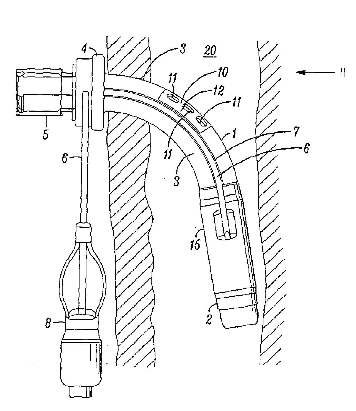
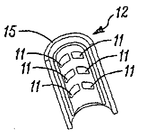
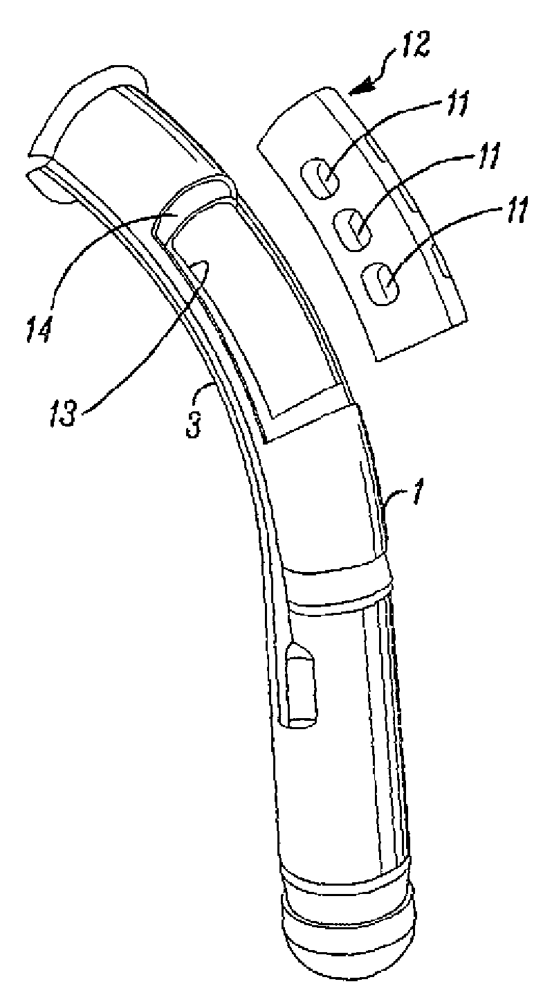
[0016] First refer to Figures 1 to 4 , a tracheostomy tube comprising a soft, flexible first material, typically silicone, and a molded shaft 1 of circular cross-section. The patient end region 2 of the cannula is straight and communicates with a curved intermediate region 3 which extends to a neck flange 4 and a conventional machine end coupling 5 . A seal in inflatable form of an envelope 15 (shown deflated) surrounds the patient end region 2 , the interior of the envelope in communication with the inflation line 6 extending along a slot 7 formed along one side of the shaft 1 . The inflation line extends through the neck flange 4 and is terminated at its machine end by a connector and an inflation indicator 8 . As described thus far, cannulation is conventional.

[0017] The cannula shaft 1 comprises a fenestrated area 10 formed substantially centrally along the curved area 3 at a position central to the tracheal airway 20 during use. The fenestrated area 10 has six open...


PUM


Abstract

A fenestrated tracheostomy tube has a shaft (1) made of a silicone or other soft material. The fenestrated region (10) located in the trachea (20) has two rows of several openings (11) along the centre line of the tube. The openings (12) are formed in a separate plate (12) of a stiffer material bonded or moulded in an aperture (13) in the shaft (1) of the tube to give the shaft extra stiffness in this region.

Description

technical field [0001] The present invention relates to a tracheostomy tube having a shaft provided with a patient end, a machine end and a fenestration along its length comprising at least one opening at a location adapted to be located within the trachea (perforated) area. Background technique [0002] Tracheostomy tubes are used to give patients oxygen during and after surgery. As the patient begins to recover, it is preferable to wean him gradually from breathing through the tube before it is completely removed. This can be accomplished by partially deflated the seal of the cannula. Alternatively, a perforated tracheostomy tube may be used that has one or more small openings in its side wall, instead of passing through the machine end of the tracheostomy tube, a part of the patient breathes through these openings and through his nose or mouth. The fenestration opening can be closed by an internal cannula, which can be removed when needed to allow gas to flow through ...

Claims


Application Information

Patent Timeline
Patent Type & Authority Applications(China)
IPC IPC(8): A61M16/04
CPCA61M16/0427A61M16/0497A61M16/044A61M16/0425A61M16/0465A61M16/0475A61M16/0479A61M16/0434A61M2205/02
Inventor D.J.考特斯
Owner SMITHS MEDICAL INT
Learn More