
Energy-saving vertical drinking fountain

An energy-saving, vertical technology, applied in beverage preparation devices, home appliances, applications, etc., can solve the problems of increasing the volume of water dispensers, better than nothing, complex structure, etc., and achieve good energy-saving effects

Active Publication Date: 2016-06-29
CHANGSHU HIBRIGHT ELECTRIC APPLIANCES
View PDF9 Cites 0 Cited by
  • Summary
  • Abstract
  • Description
  • Claims
  • Application Information

AI Technical Summary

Problems solved by technology

Compared with CN2155523Y, this CN201005513Y provides cold boiled water that has been boiled, so it can meet the hygienic requirements. However, in order to cool down the water that is led to the cold tap by the water pipe, the cold water pipe will also significantly increase the capacity of the water dispenser. bulky and tends to complicate the structure
[0006] In addition to the deficiencies mentioned above, the above two patents also have the disadvantage of wasting energy, because the heat released by the high-temperature hot water in the process of being cooled to cold boiled water is insufficient to be utilized by the tap water diversion pipeline to be heated, that is, It cannot reflect the effective heat exchange of each other. Although the measures of immersing the pipes providing cold boiled water in the cold water tank in the two patents can increase the water temperature of the cold water tank to a certain extent, due to the volume of the cold water tank and the distance between the pipes providing cold boiled water The volume disparity is large, so it is often better to increase the water temperature of the cold water tank than nothing, and the water in the cold water tank cannot be supplied to the heating water tank at one time, and only when the heating water tank needs replenishment is the cold water tank replenished to the heating water tank

Method used


Image

  • Energy-saving vertical drinking fountain
  • Energy-saving vertical drinking fountain

Examples


Embodiment Construction

[0022] In order to enable examiners of the Patent Office, especially the public, to more clearly understand the technical essence and beneficial effects of the present invention, the applicant will describe in detail in the form of examples below, but the description of the examples is not intended to describe the solution of the present invention. As a limitation, any equivalent transformations made according to the concept of the present invention that are merely formal rather than substantive should be regarded as the technical solution scope of the present invention.

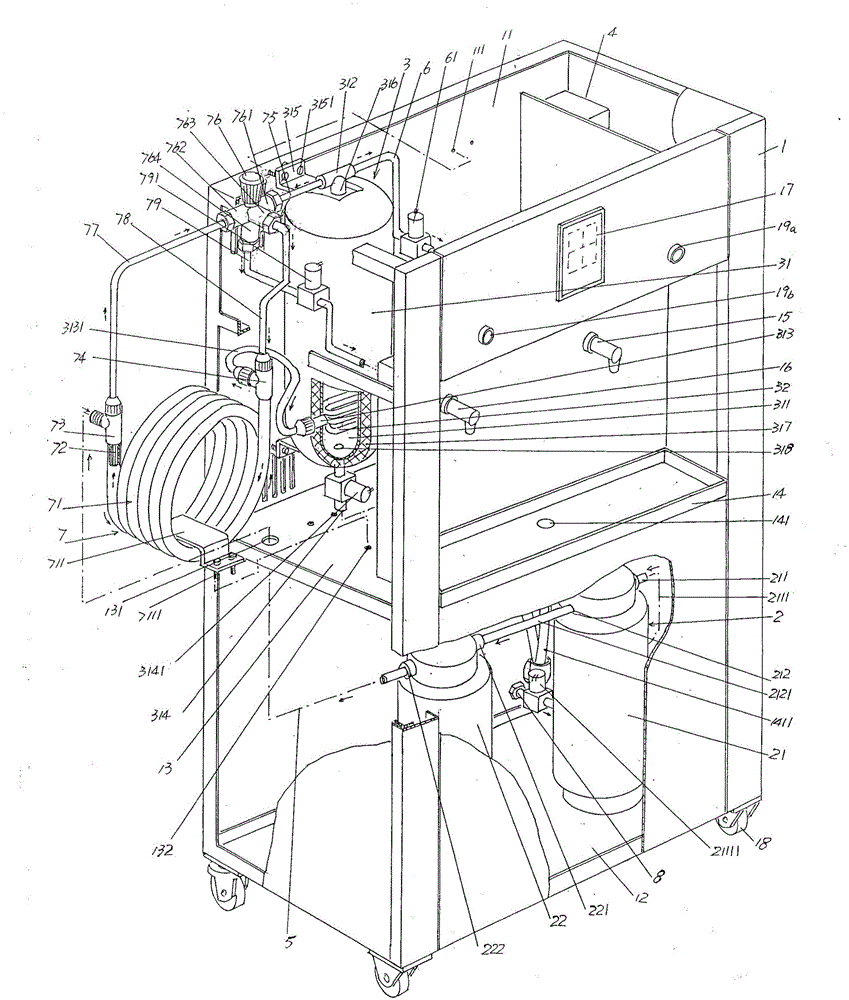
[0023] See figure 1 ,in figure 1 Shown in: a cabinet 1, the cabinet 1 is a vertical cabinet, the upper part of the cabinet 1 is formed with a cabinet upper cavity 11, and the lower part is formed with a cabinet lower cavity 12, the upper and lower cabinets The cavities 11 and 12 are separated by the cabinet compartment partition plate 13, and the side in the height direction of the cabinet 1 is the side facing t...


PUM


Abstract

The invention discloses an energy-saving type vertical type drinking water table and belongs to the technical field of drinking water devices. The energy-saving type vertical type drinking water table comprises a cabinet, a water treatment mechanism, a water heating mechanism, an electric controller, a treated water outlet pipe and a hot water outlet pipe. An upper cabinet cavity is formed in the upper portion of the cabinet, a lower cabinet cavity is formed in the lower portion of the cabinet, the upper cabinet cavity and the lower cabinet cavity are separated through a cabinet cavity separation board, a water collection disc is arranged on one side of the cabinet in the height direction, and the positions, corresponding to the positions above the water collection disc, are provided with a hot water faucet and a cold boiled water faucet. The water treatment mechanism is arranged in the lower cabinet cavity and is connected with a water source pipeline. The water heating mechanism is arranged in the upper cabinet cavity. The electric controller is arranged in the lower cabinet cavity and is in electric control connection with the water treatment mechanism and the water heating mechanism. The treated water outlet pipe is connected with the water treatment mechanism. One end of the hot water outlet pipe is connected with the water heating mechanism, and the other end of the hot water outlet pipe is connected with the hot water faucet. The energy-saving type vertical type drinking water table is characterized by further comprising a heat transfer mechanism arranged in the upper cabinet cavity and simultaneously connected with the cold boiled water faucet, the water heating mechanism and the treated water outlet pipe. The energy-saving type vertical type drinking water table can meet selective requirements of drinkers and represent a good energy-saving effect.

Description

Technical field [0001] The invention belongs to the technical field of drinking water devices, and specifically relates to an energy-saving vertical drinking water table. Background technique [0002] The aforementioned vertical drinking fountains are also called vertical drinking fountains or vertical drinking platforms, or even cabinet drinking fountains. Such drinking fountains are widely used in schools, conference centers, offices, stadiums, industrial and mining enterprises, and personnel exchanges. Frequent public places such as stations, waiting rooms, airport terminals, etc. [0003] The prior art vertical drinking fountains usually only provide high-temperature boiled water but cannot provide boiled cold boiled water, so it is difficult to meet people's selection requirements for drinking boiled water at different temperatures in actual use. Because, in places where passengers come and go in a hurry, such as stations and airports, drinking cold boiled water can not only ...

Claims


Application Information

Patent Timeline
Patent Type & Authority Patents(China)
IPC IPC(8): A47J31/00A47J31/54
Inventor 成志方祝冬初
Owner CHANGSHU HIBRIGHT ELECTRIC APPLIANCES
Learn More