
Optical fiber latching current protective device

A protection device and blocking current technology, which is applied in the direction of emergency protection circuit devices, circuit devices, electrical components, etc., can solve the problems of unequipped protection devices, protection devices that are difficult to meet the selectivity requirements, and unsatisfactory applications, so as to meet the selectivity requirements Effect

Inactive Publication Date: 2012-05-09
HUZHOU ELECTRIC POWER ADMINISTATION ZHEJIANG PROV +2
View PDF8 Cites 0 Cited by
  • Summary
  • Abstract
  • Description
  • Claims
  • Application Information

AI Technical Summary

Problems solved by technology

In the current smart distribution network construction process, there are certain difficulties in the selection of protection devices. Generally, protection devices are not equipped, which will reduce the power supply reliability of the power grid.
According to the characteristics of the distribution network, it is generally more appropriate to choose inverse time protection. However, due to the large number of branches in the domestic distribution network, the existing protection devices are difficult to meet the selectivity requirements, and the application has not been ideal.

Method used


Image

  • Optical fiber latching current protective device
  • Optical fiber latching current protective device

Examples


Embodiment Construction

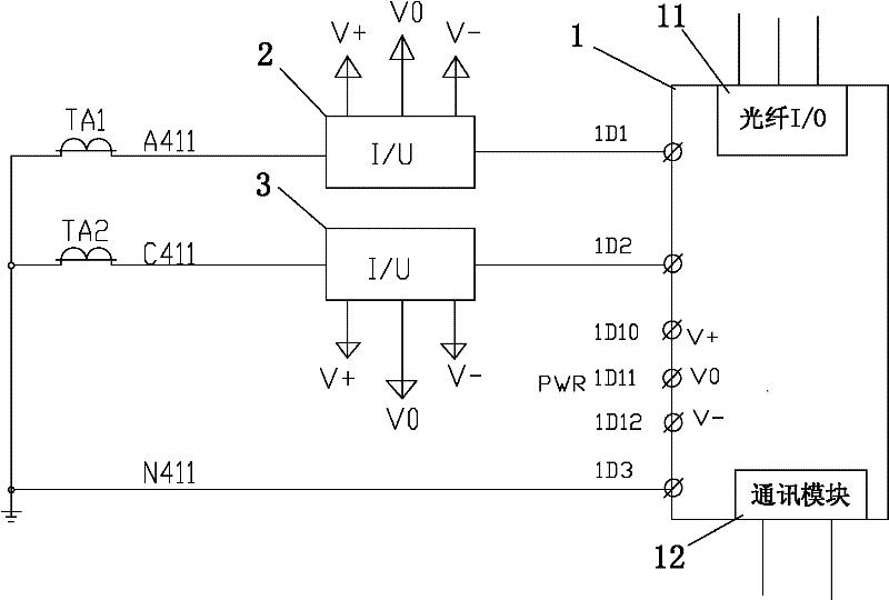
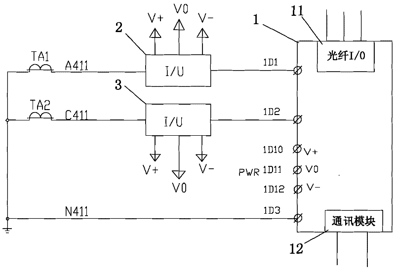
[0014] refer to figure 1 , the present invention is an optical fiber blocking current protection device, including a sampling circuit and a processing module 1 for detecting signals of the sampling circuit, and the communication between the processing module 1 and the superior protection device is completed through the optical fiber I / O module 11. The optical fiber I / O module 11 is located in the processing module 1, and the processing module 1 is also provided with a communication module 12, the communication module 12 can realize optical fiber Ethernet and RS485 transmission; the processing module 1 is an intelligent electronic device IED, which is mainly responsible for protection, control and Monitor the base unit.

[0015] The sampling circuit includes a first current transformer TA1 and a second current transformer TA2, a first I / U conversion module 2 and a second I / U conversion module 3, and the output terminal A411 of the first current transformer TA1 is connected to t...


PUM


Abstract

The invention discloses an optical fiber latching current protective device which comprises a sampling circuit and a processing module used for detecting a signal of the sampling circuit as well as an optical fiber I / O (input / output) module used for realizing communication between the processing module and a superior protective device. Signal is ensured to be rapidly transmitted between the superior protective device and a subordinate protective device by virtue of rapidity of optical fiber signal transmission of the optical fiber I / O module, thus selectivity requirement of setting of the protective device is met.

Description

technical field [0001] The invention relates to an optical fiber blocking current protection device, which belongs to the field of power system equipment. Background technique [0002] Power grid technology has entered the era of smart grid, and distribution network is also an important part of smart grid. There are certain difficulties in the selection of protection devices in the construction process of the current smart distribution network. Generally, protection devices are not equipped, which will reduce the power supply reliability of the power grid. According to the characteristics of the distribution network, it is generally more appropriate to choose inverse time-limit protection. However, due to the large number of branches in the domestic distribution network, the existing protection devices are difficult to meet the selectivity requirements, and the application has not been ideal. Contents of the invention [0003] The problem to be solved by the present inven...

Claims


Application Information

Patent Timeline
IPC IPC(8): H02H7/26H02J13/00
CPCY04S40/124Y04S10/20Y02E60/725Y02E60/7838Y02E60/00
Inventor 张从柱
Owner HUZHOU ELECTRIC POWER ADMINISTATION ZHEJIANG PROV
Learn More