Position matching method for underwater vehicle terrain aided inertial navigation system

A technology of inertial navigation system and underwater submersible, which is applied in the field of position matching of underwater submersible terrain-assisted inertial navigation system, and can solve problems such as incorrect range of search area

Active Publication Date: 2015-03-04
SOUTHEAST UNIV
View PDF6 Cites 20 Cited by
  • Summary
  • Abstract
  • Description
  • Claims
  • Application Information

AI Technical Summary

Problems solved by technology

This method is desirable when the initial error of inertial navigation is not large. When t

Method used


Image

  • Position matching method for underwater vehicle terrain aided inertial navigation system
  • Position matching method for underwater vehicle terrain aided inertial navigation system
  • Position matching method for underwater vehicle terrain aided inertial navigation system

Examples


Embodiment Construction

[0033] The technical solutions of the present invention will be described in detail below, but the protection scope of the present invention is not limited to the embodiments.

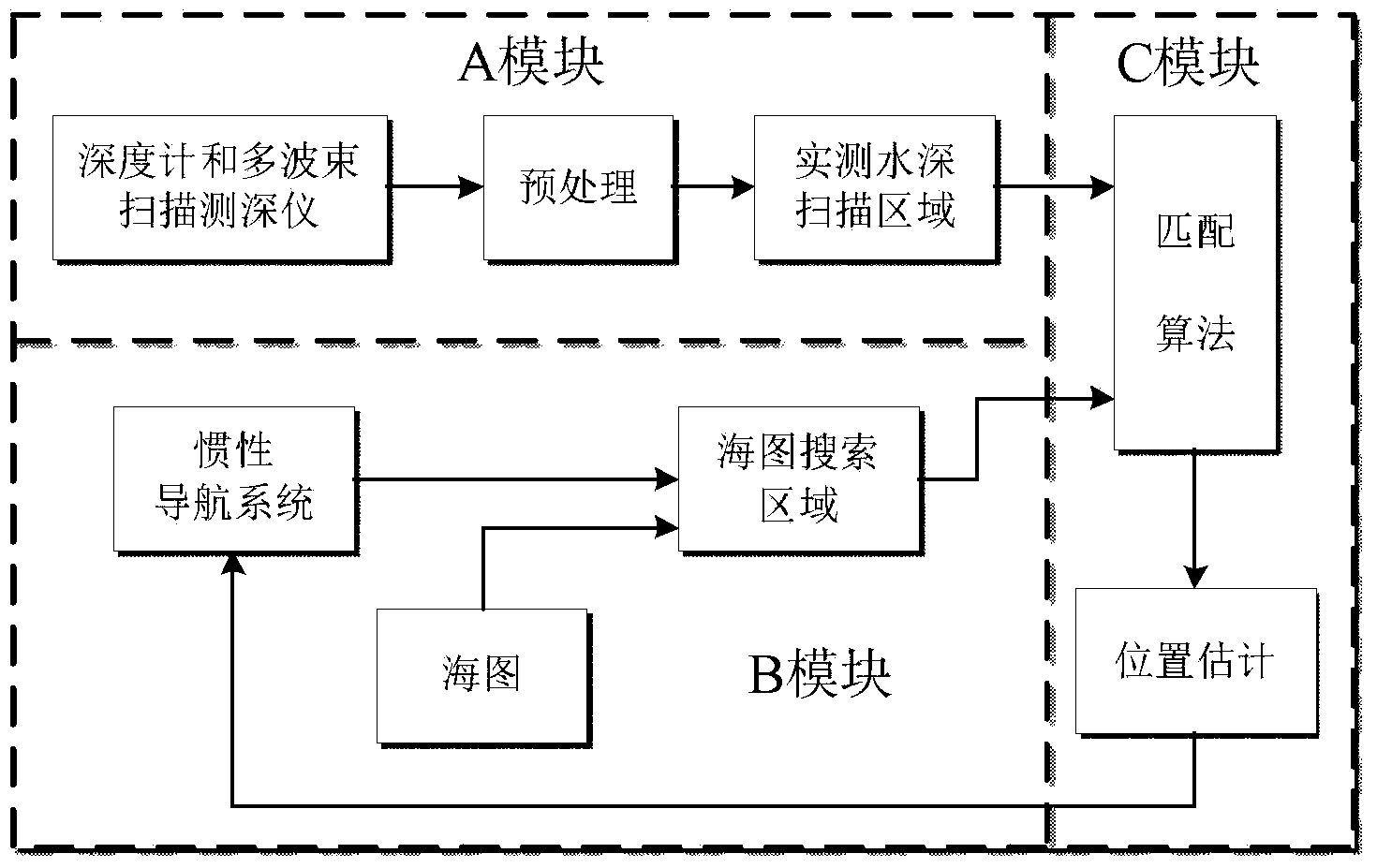
[0034] Such as figure 1 As shown, the traditional terrain-aided inertial navigation system generally includes three modules A, B and C. The main purpose of module A is to use the depth gauge and multi-beam scanning depth sounder equipped on the submersible to measure the water depth value in the navigation area of ​​the submersible; the main purpose of module B is to use the output position information of the inertial navigation system equipped on the submersible to calculate The distance between adjacent measurement moments is combined with the existing chart to obtain the chart search area; the purpose of the C module is to use the matching algorithm to finally obtain the position estimate of the submersible and correct the position parameters of the inertial navigation system.

[0035] The inventio...


PUM


Abstract

The invention discloses a position matching method for an underwater vehicle terrain aided inertial navigation system. The method includes: 1) after entering a nautical chart coverage area, utilizing a depth gauge and a multibeam scanning depth finder to measure the water depth value of a navigation area within the starting time period Delta t1 of an underwater vehicle; 2) calculating the water depth cumulative histogram H1 and terrain roughness Kr1 of the time period Delta t1, and a next water depth measurement time period Delta t2; 3) determining the possible position set L1 of the underwater vehicle at the time of Delta t1/2; and 4) measuring the water depth value of the underwater vehicle's navigation area within the time period Delta tn (n=2, 3,..., N), and calculating the water depth cumulative histogram Hn and terrain roughness Krn of the time period Delta tn, and next water depth measurement time period Delta tn+1, etc. Being an autonomous matching method, the method provided by the invention has the characteristics of high precision and good robustness, and can be applied to terrain, terrestrial magnetism or gravity aided inertial navigation and positioning.

Description

technical field [0001] The invention relates to a topography matching method of an underwater submersible, which is mainly aimed at the position matching method of the topography-assisted inertial navigation system of the underwater submersible. Background technique [0002] After the underwater submersible has sailed for a long time, the position output by the pure inertial navigation system has accumulated a large error. Considering the actual situation of safety, concealment and long-term underwater operation, passive navigation technology using geophysical field-assisted inertial navigation mainly includes inertial / terrain, inertial / gravity and inertial / geomagnetic integrated navigation. The basic principle is to measure the geophysical field data on the navigation track through the sensors equipped on the submersible, and then match it with the existing database to determine the best position of the submersible. [0003] The terrain matching method was first applied in...

Claims


Application Information

Patent Timeline
IPC IPC(8): G01C21/16G01C21/20
CPCG01C21/165G01C21/20
Inventor 程向红周玲陆源冉昌艳王磊朱倚娴
Owner SOUTHEAST UNIV
Why Eureka
Try Eureka