Embedded touch screen and display device

An embedded touch screen and display control technology, which is applied in the direction of instruments, calculations, electrical digital data processing, etc., can solve problems such as insufficient time

Active Publication Date: 2015-03-04
BOE TECH GRP CO LTD +1
View PDF4 Cites 14 Cited by
  • Summary
  • Abstract
  • Description
  • Claims
  • Application Information

AI Technical Summary

Problems solved by technology

[0003] In view of this, the embodiment of the present invention provides an in-cell touch screen and a display device, which are used to solve various display problems caused by insufficient time and touch problem

Method used


Image

  • Embedded touch screen and display device
  • Embedded touch screen and display device
  • Embedded touch screen and display device

Examples


Embodiment Construction

[0029] The specific implementation manners of the in-cell touch screen and the display device provided by the embodiments of the present invention will be described in detail below with reference to the accompanying drawings.

[0030] The thickness and shape of each film layer in the drawings do not reflect the real scale, and the purpose is only to illustrate the content of the present invention.

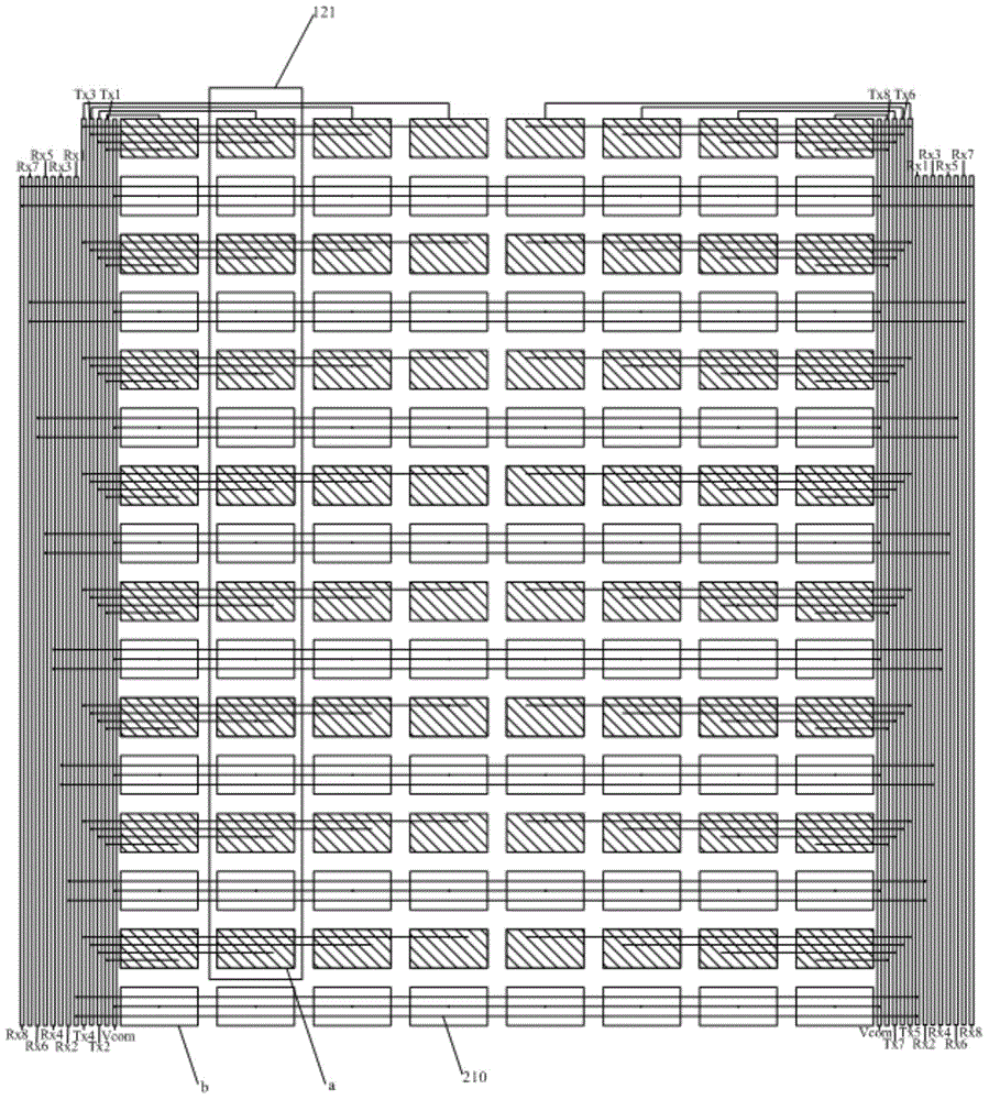
[0031] figure 2 A schematic longitudinal cross-sectional view of an in-cell touch screen provided by an embodiment of the present invention. An embedded touch screen provided by an embodiment of the present invention, such as figure 2 As shown, it includes: an array substrate 100 having gate lines 110 and a common electrode layer 120, and an opposite substrate 200 opposite to the array substrate 100;

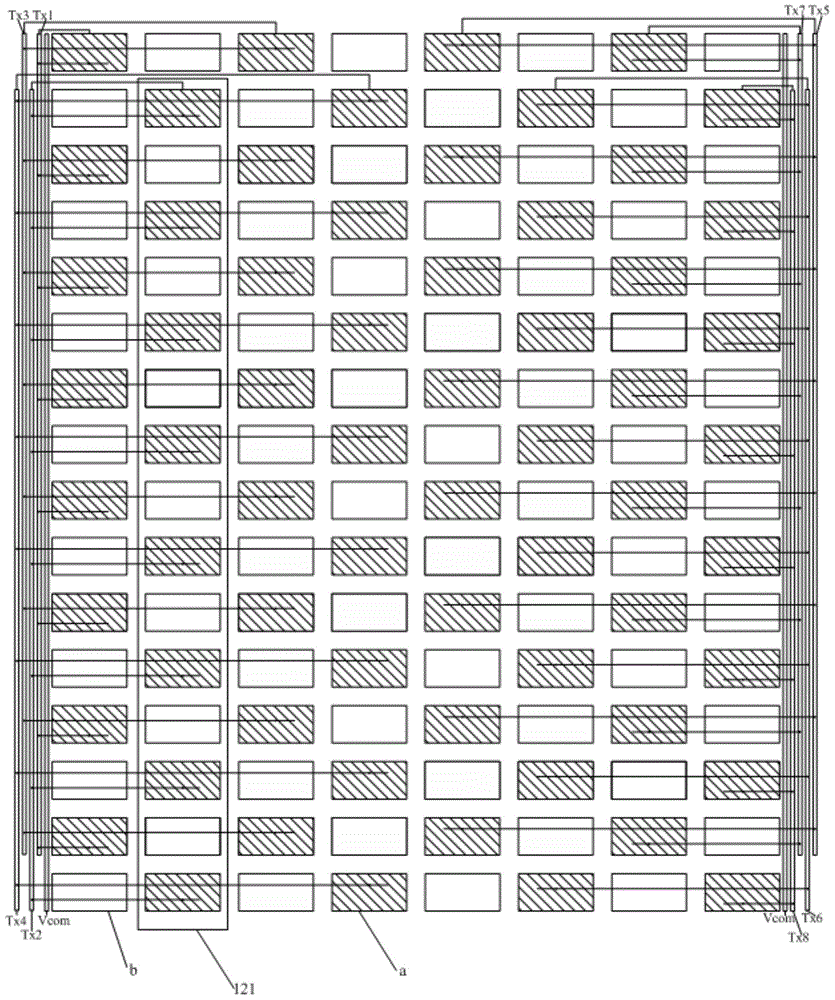
[0032] Such as Figure 3a and Figure 3b As shown, the common electrode layer 120 of the array substrate 100 is divided into a plurality of sub-electrodes ( Figure 3a and F...


PUM


Abstract

The invention discloses an embedded touch screen and a display device. A public electrode layer in an array substrate is divided into multiple sub-electrodes distributed in multiple arrays; the sub-electrodes arranged at intervals in each row and serving as touch driving sub-electrodes form a touch driving electrode, and the rest sub-electrodes serve as public sub-electrodes; a touch sensing electrode projected in a region in which the public sub-electrodes are positioned is arranged on an opposite substrate. when grid lines covered by the sub-electrodes in each row are scanned, the sub-electrodes in the row load public electrode signals, the touch driving sub-electrodes of the sub-electrodes in other rows load touch driving signals, and the public sub-electrodes of the sub-electrodes in other rows load the public electrode signals, i.e., when one row of sub-electrodes is used for displaying, the sub-electrodes in other rows are used for touch driving. By virtue of the driving mode, the purpose of simultaneously performing displaying and touch control is realized, and various display problems and touch problems caused by deficiency of time during time-sharing driving can be avoided under the condition that high resolution is ensured.

Description

technical field [0001] The invention relates to the field of display technology, in particular to an embedded touch screen and a display device. Background technique [0002] At present, the existing in-cell touch screen uses the principle of mutual capacitance to detect the touch position of the finger; wherein, the touch electrode pattern is generally added to the touch screen. In order to avoid mutual interference between the touch signal loaded by the touch electrode and the normal display signal in the touch screen, the touch function and display function are generally driven by time-sharing, such as figure 1 As shown, a frame time (Vsync) is divided into a touch time period (Touch) and a display time period (Display). The data signal and the gate lines Gn-2, Gn-1, Gn, G1, G2 and G3 are only displayed The time period works, and the touch signal only works in the touch time period; in this way, the time allocated to the touch time period and the display time period in e...

Claims


Application Information

Patent Timeline
IPC IPC(8): G06F3/041
CPCG06F3/041G06F2203/04111G06F3/0412G06F3/04164G06F3/04166G06F3/0443G06F3/047
Inventor 王海生董学
Owner BOE TECH GRP CO LTD
Why Eureka
Try Eureka