Supercharge Your Innovation With Domain-Expert AI Agents!

rocker arm

A main body and valve technology, applied in the field of rocker arm, can solve complex and expensive problems

Active Publication Date: 2017-05-17
EATON SRL
View PDF8 Cites 1 Cited by
  • Summary
  • Abstract
  • Description
  • Claims
  • Application Information

AI Technical Summary

Problems solved by technology

This is a complex and relatively expensive process

Method used


Image

  • rocker arm
  • rocker arm
  • rocker arm

Examples


Embodiment Construction

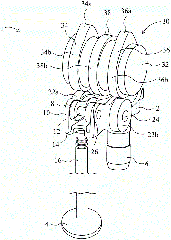
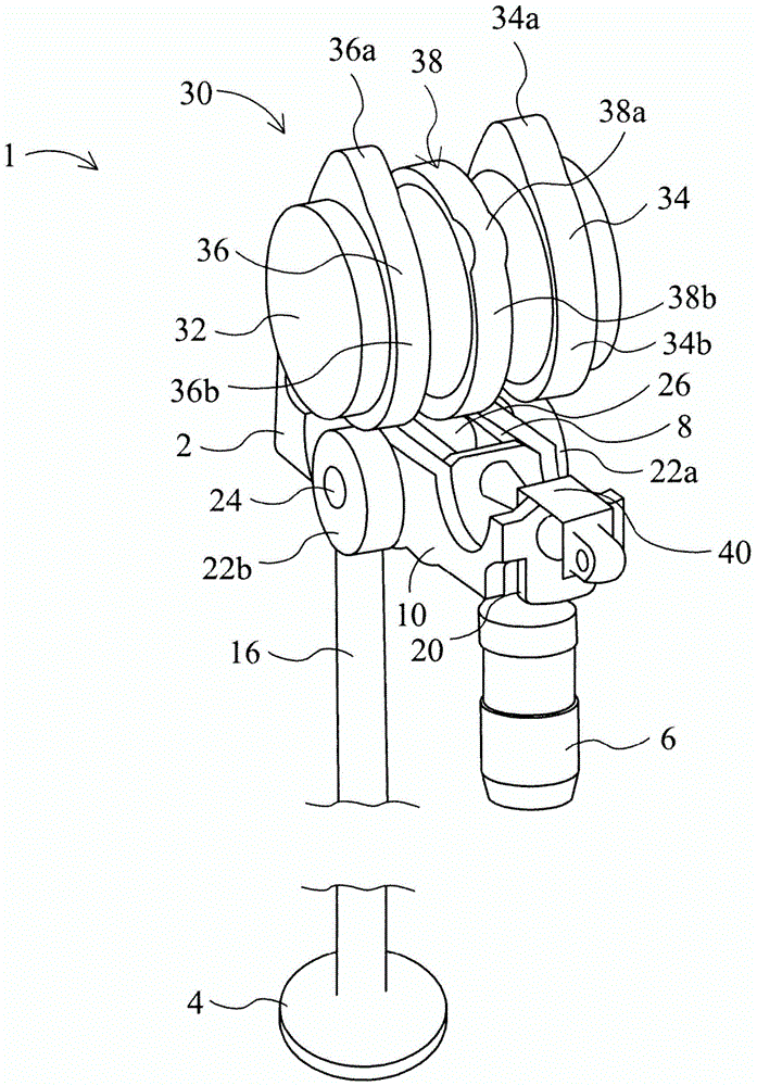
[0016] see first figure 1 and figure 2 , the valve train assembly 1 includes a double-lift rocker arm 2 , an engine valve 4 for an internal combustion engine cylinder (not shown), and a lash adjuster 6 . The rocker arm 2 comprises an inner body or arm 8 and an outer body or arm 10 . The inner body 8 is pivotally mounted on an axle 12 for connecting the inner body 8 and the outer body 10 . The first end 14 of the outer body 10 engages the valve stem 16 of the valve 4, and the second end 20 of the outer body 10 is mounted for pivotal movement on the lash adjuster 6, which is supported on the engine block (not shown). )middle. The lash adjuster 6 can be, for example, a hydraulic lash adjuster, and is used to adjust the clearance between various components in the valve train assembly 1 . Lash adjusters are known per se, so the lash adjuster 6 will not be described in detail.

[0017] The rocker arm 2 is provided with a pair of main lift rollers 22a and 22b rotatably mounted ...


PUM


Abstract

a rocker arm comprising a first roller for engaging a first rotatable cam surface whereby at least a portion of the rocker arm can be pivoted by at least the first rotatable cam surface to move the valve to cause a first valve action, Also comprising other rollers for engaging other rotatable cam surfaces whereby at least a portion of the rocker arm may be pivoted by said other rotatable cam surfaces to move the valves to cause a second valve action different from First valve action. The rocker arm is configurable in a first mode of operation in which one of the first valve action and a second valve action occurs, and in a second mode of operation in which the first valve action and the second valve action occur. Both valve actions or the other of the first valve action and the second valve action occurs.

Description

technical field [0001] The present invention relates to rocker arms. Background technique [0002] Dual-lift rocker arms are known for controlling valve action by alternating between at least two or more modes of operation. Such rocker arms typically comprise a plurality of bodies, such as inner and outer arms, which are locked together to provide one mode of operation, and which are unlocked and thus able to pivot relative to each other to provide another mode of operation. This so-called type II valve train (ie end-of-arm pivoting rocker arm, overhead cam) is the most commonly used valve train in both modern gasoline and diesel internal combustion engines. Dual-lift rocker arms for this type of valve train typically employ a three-cam type camshaft, where the first and second cams control one valve lift, and the third cam controls the other valve lift. Typically in this arrangement, the outer arm of the dual-lift rocker arm is equipped with a pair of curved metal pads, e...

Claims


Application Information

Patent Timeline
IPC IPC(8): F01L1/18F01L13/00
CPCF01L1/04F01L1/053F01L1/18F01L1/185F01L1/34F01L13/0021F01L13/0036F01L2001/186F01L2305/00F02M26/01F01L1/047F01L13/0047F01L2001/467F02D13/0207F02D13/0273
Inventor M·赛瑟
Owner EATON SRL
Features
  • R&D
  • Intellectual Property
  • Life Sciences
  • Materials
  • Tech Scout
  • Unparalleled Data Quality
  • Higher Quality Content
  • 60% Fewer Hallucinations
Learn More