Anti-theft door with hydraulic locking device

A locking device and technology of anti-theft doors, applied in the field of anti-theft doors

Inactive Publication Date: 2015-03-11
安徽明辉门业有限公司
View PDF6 Cites 4 Cited by
  • Summary
  • Abstract
  • Description
  • Claims
  • Application Information

AI Technical Summary

Problems solved by technology

[0002] Anti-theft door is a new type of door industry widely used in commerce and industry, but the current anti-theft door only increases its strength in structure, and the self-locking device still uses the traditional anti-theft lock, which can still function under strong external force. It is easy to open, but does not really achieve the anti-theft effect. In view of the above defects, it is necessary to design a hydraulic locking device anti-theft door

Method used


Image

  • Anti-theft door with hydraulic locking device
  • Anti-theft door with hydraulic locking device

Examples


Embodiment Construction

[0023] In the following, numerous specific details are set forth in order to provide a thorough understanding of the concepts underlying the described embodiments. It will be apparent, however, to one skilled in the art that the described embodiments may be practiced without some or all of these specific details. In other instances, well known processing steps have not been described in detail.

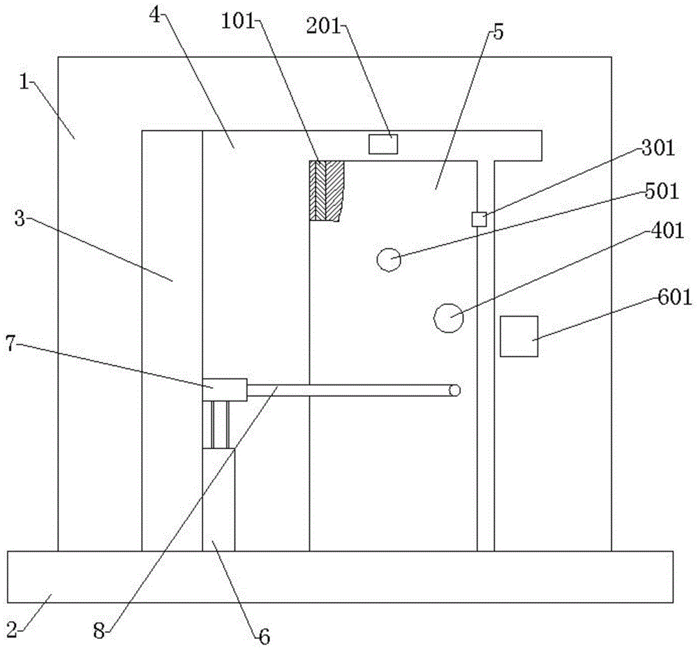
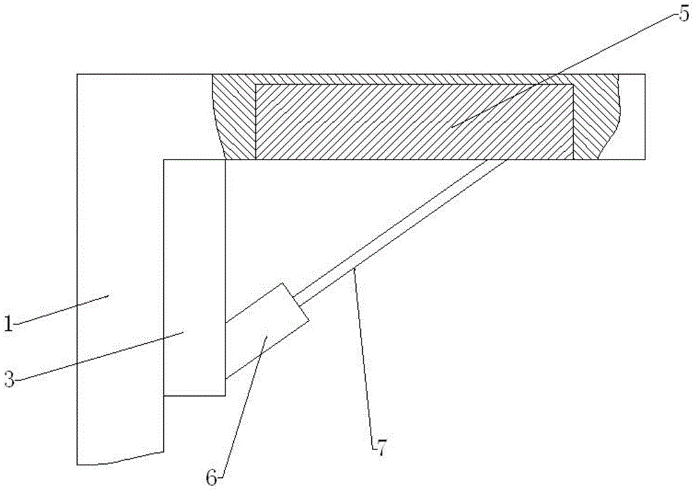
[0024] Such as figure 1 , figure 2 As shown, including installation wall 1, floor 2, vertical board 3, door frame 4, anti-theft door 5, hydraulic controller 6, hydraulic cylinder 7, pull rod 8, rotating shaft 101, camera 201, automatic lock 301, safety door lock 401, observation Mirror 501, cipher, vertical plate 3 is located at the left side of the front end of the installation wall 1, the two are connected by threads, the door frame 4 is located at the center of the right end of the vertical plate 3, the two are connected by welding, the anti-theft door 5 is located at the inner ...


PUM


Abstract

The invention discloses an anti-theft door with a hydraulic locking device. The anti-theft door with the hydraulic locking device comprises an installing wall and a floor and is characterized by comprising a vertical plate, a doorframe, an anti-theft door, a hydraulic controller, a hydraulic cylinder and a pull rod, wherein the vertical plate is positioned at the left side of the front end of the installing wall, the vertical plate and the installing wall are in threaded connection, the doorframe is positioned at the central part of the right end of the vertical plate, the doorframe and the vertical plate are in welding connection, the anti-theft door is positioned at the central part inside the doorframe, the anti-theft door and the doorframe are movably connected, the hydraulic controller is positioned at the central part of the lower side at the right end of the vertical plate, the hydraulic controller and the vertical plate are in threaded connection, the hydraulic cylinder is positioned at the central part of the right end of the vertical plate, the hydraulic cylinder and the vertical plate are in threaded connection, the pull rod is positioned at the central part of the front end of the hydraulic cylinder, and the pull rod and the hydraulic cylinder are in threaded connection. Compared with the prior art, a person controls the hydraulic controller by using a remote controller to control the hydraulic cylinder to control the pull rod to extend and retract, so that the opening and the closing of the anti-theft door are achieved; the pressure magnitude of the hydraulic cylinder can be adjusted through a hydraulic press; the larger an external force is, the larger the pressure generated by the hydraulic controller is, so that completely self-locking and anti-theft functions are achieved.

Description

technical field [0001] The invention relates to an anti-theft door, in particular to an anti-theft door with a hydraulic locking device. Background technique [0002] Anti-theft door is a new type of door industry widely used in commerce and industry, but the current anti-theft door only increases its strength in structure, and the self-locking device still uses the traditional anti-theft lock, which can still function under strong external force. Open easily, do not really reach anti-theft effect, in view of above-mentioned defective, be necessary to design a kind of hydraulic locking device anti-theft door really. Contents of the invention [0003] The technical problem to be solved by the present invention is to provide an anti-theft door with a hydraulic locking device to solve the problem that ordinary anti-theft doors can be easily opened under strong external force, but cannot achieve complete anti-theft effect. Contents of the invention [0004] The technical pr...

Claims


Application Information

Patent Timeline
Patent Type & Authority Applications(China)
IPC IPC(8): E06B5/11E05B51/02
Inventor 张满安
Owner 安徽明辉门业有限公司
Why Eureka
Try Eureka