A direction adjustment equipment accessory in the medical field

A technology for direction adjustment and equipment, applied in the direction of mechanical equipment, shafts, bearings, bearings, etc., can solve the problems of complex bracket structure, troublesome operation, difficult control, etc., and achieve the effect of simple structure, easy control and convenient operation of the device

Active Publication Date: 2020-10-09
ZHEJIANG CHAOAN MECHANICAL CO LTD
View PDF5 Cites 0 Cited by
  • Summary
  • Abstract
  • Description
  • Claims
  • Application Information

AI Technical Summary

Problems solved by technology

[0003] In the existing medical field, the use of a stent with a universal function to control the spatial position requires multiple hinges to realize. If it is realized simply by using two-dimensional hinges, multiple two-dimensional articulated devices are required, which will cause the structure of the stent to be complicated. control, and it is cumbersome to operate. If the ball joint is used to connect, only a few ball joints are needed to realize the ball joint. The structure of the ball joint is simple, the operation is convenient, and it is easy to control; In the process, the ball joint needs to be self-locking, so it is necessary to design a self-locking ball joint for brackets in the medical field

Method used


Image

  • A direction adjustment equipment accessory in the medical field
  • A direction adjustment equipment accessory in the medical field
  • A direction adjustment equipment accessory in the medical field

Examples


Embodiment Construction

[0047] The specific implementation manners of the present invention will be further described in detail below in conjunction with the accompanying drawings and embodiments. The following examples or drawings are used to illustrate the present invention, but not to limit the scope of the present invention.

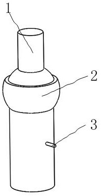
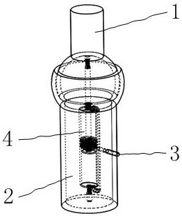
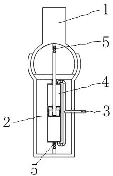
[0048] Such as figure 1 , 2 As shown, it includes a first connecting rod 1, a second connecting rod 2, a hydraulic cylinder 4, a first fixed rod 9, and a second fixed rod 10, wherein as Figure 5 As shown, one end of the first connecting rod 1 has a first spherical joint shell 7, the second connecting rod 2 is hollow, and one end of the second connecting rod 2 has a second spherical joint shell 8, and the outer circular surface of the second connecting rod 2 There is a circular hole 6; the first connecting rod 1 is hinged with the second connecting rod 2 through the cooperation of the first spherical joint housing 7 and the second spherical joint housing 8 on the second c...


PUM


Abstract

The invention belongs to the technical field of universal rotation of medical equipment, and in particular relates to a direction adjustment equipment accessory in the medical field, which includes a first connecting rod, a second connecting rod, and a hydraulic cylinder. The universal joint device has all the functions of a ball joint, Compared with the traditional ball joint, this device can control the relative swing and rotation between the first connecting rod and the second connecting rod by controlling the switching valve between the second liquid pipe and the elastic liquid bag; so that the first connecting rod and the second connecting rod to achieve self-locking function; when the piston rod designed in the present invention rotates relative to the piston shell, the clamping plate installed on the upper end surface of the piston rod outer casing plays a limiting role on the limit plate on the piston rod, The rotation angle is less than 360 degrees, which prevents the internal thread on the threaded sleeve installed on the piston inner shell from being disengaged from the external thread on the piston rod during the rotation of the piston rod relative to the piston inner shell, which improves the safety of the device .

Description

[0001] Technical field [0002] The invention belongs to the technical field of universal rotation of medical equipment, and in particular relates to a direction adjustment equipment accessory in the medical field. Background technique [0003] In the existing medical field, the use of a stent with a universal function to control the spatial position requires multiple hinges to realize. If it is realized simply by using two-dimensional hinges, multiple two-dimensional articulated devices are required, which will cause the structure of the stent to be complicated. control, and it is cumbersome to operate. If the ball joint is used to connect, only a few ball joints are needed to realize the ball joint. The structure of the ball joint is simple, the operation is convenient, and it is easy to control; In the process, the ball joint needs to be self-locked, so it is very necessary to design a self-locking ball joint for the bracket in the medical field. [0004] The invention des...

Claims


Application Information

Patent Timeline
Patent Type & Authority Patents(China)
IPC IPC(8): F16C11/06F16C11/10F16C9/00F15B15/08
CPCF16C11/0609F16C11/0695F16C11/10
Inventor 张楼锋
Owner ZHEJIANG CHAOAN MECHANICAL CO LTD
Why Eureka
Try Eureka