Electromagnetic relay manual test switch structure convenient to operate and electromagnetic relay

A technology of electromagnetic relay and manual testing, which is applied in the direction of electromagnetic relay, detailed information of electromagnetic relay, switch operated by ground fault current, etc. It can solve problems such as easy misoperation by testers, inconvenient operation by testers, and insufficient intuitive knob status. Achieve the effect of convenient assembly and disassembly, convenient operation and intuitive status

Pending Publication Date: 2019-11-26
XIAMEN HONGFA ELECTROACOUSTIC CO LTD
View PDF0 Cites 0 Cited by
  • Summary
  • Abstract
  • Description
  • Claims
  • Application Information

AI Technical Summary

Problems solved by technology

For a relay with only normally closed static contacts, if the resistance between the pins corresponding to the moving contacts and the pins corresponding to the normally closed static contacts is infinite, it means that the moving contacts and the normally closed static contacts can be disconnected normally. Open, the relay function is normal; if the resistance between the pin corresponding to the moving contact and the pin corresponding to the normally closed static contact is close to zero, it means that the moving contact and the normally closed static contact cannot be disconnected normally, indicating that the relay function Abnormal, that is, the relay has failed
[0003] The above test switches are mostly implemented with knobs. Since the knobs can be rotated 360°, and the knobs are mostly designed as circular structures, the state of the knobs is not intuitive enough, and testers are prone to misuse.
In addition, with the knob method, the tester often needs to use at least two fingers to turn the knob, or, in a narrow space, the tester needs to use tools to turn the knob, which makes the operation more inconvenient for the tester

Method used


Image

  • Electromagnetic relay manual test switch structure convenient to operate and electromagnetic relay
  • Electromagnetic relay manual test switch structure convenient to operate and electromagnetic relay
  • Electromagnetic relay manual test switch structure convenient to operate and electromagnetic relay

Examples


Embodiment Construction

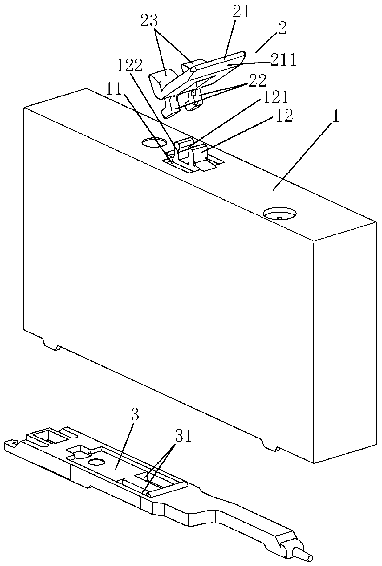
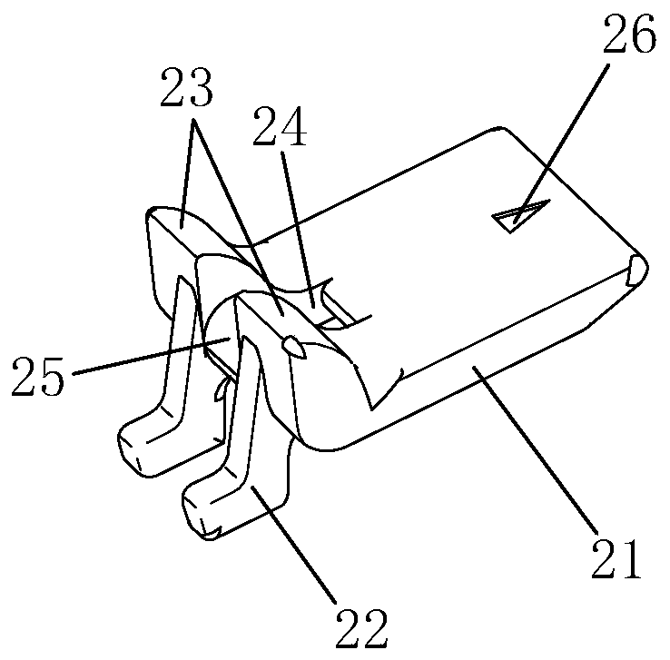
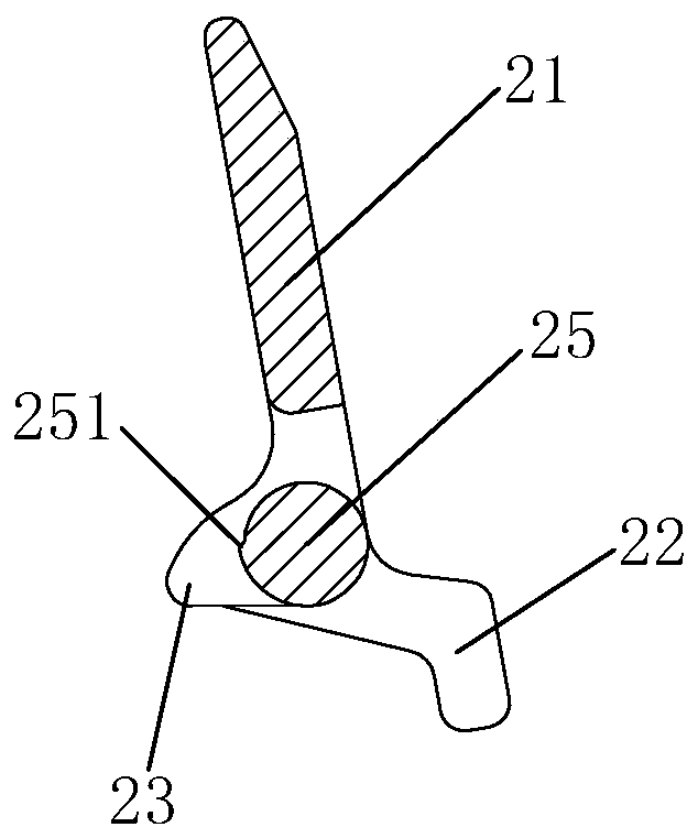
[0035] Examples, see Figure 1-Figure 6 As shown, a conveniently operated electromagnetic relay manual test switch structure of the present invention includes an electromagnetic relay shell 1 and a toggle button 2, the toggle button 2 is rotatably arranged on the top of the shell 1, and the toggle button 2 partially extends into the and cooperate with the push card 3 of the electromagnetic relay to drive the push card 3 to move axially, thereby driving the moving reed of the electromagnetic relay, so that the moving contact on the moving reed contacts or breaks with the corresponding static contact Open (the electromagnetic relay function is normal). The toggle button 2 can be toggled to the open or closed state, and when the toggle button 2 is turned on, the toggle button 2 drives the push card 3 to move along the direction of the moving reed that drives the electromagnetic relay, and when the toggle button 2 is turned off, the toggle button 2 Release the push card, and the ...


PUM


Abstract

The invention discloses an electromagnetic relay manual test switch structure convenient to operate and an electromagnetic relay. The manual test switch structure comprises an electromagnetic relay shell and also comprises a shift knob, wherein the shift knob is rotatably arranged on the shell, the shift knob locally extends to the shell and is matched with a push clamp of the electromagnetic relay, the shift knob can be shifted to an open or closed state, the push clamp is driven to move along a direction of driving a movable spring sheet of the electromagnetic relay by the shift knob when the shift knob is opened, and the push clamp is released by the shift knob when the shift knob is closed. The shift knob is employed to substitute a knob and is used as a test switch of the electromagnetic relay, the state is more intuitive, a detector is difficult to operate by mistake, a tester is also more convenient to operate, labor is saved, the tester can operate by a single finger, and no tool is needed in a narrow space.

Description

technical field [0001] The invention relates to the field of relays, in particular to a conveniently operated electromagnetic relay manual test switch structure and the electromagnetic relay. Background technique [0002] At present, in the actual application process of the small control relays of the prior art, once the application equipment fails, in addition to the fault detection of the equipment itself, the abnormality detection of the relay is also required to determine whether the equipment failure is caused by the abnormal operation of the relay. When performing anomaly detection on relays, since the application equipment can no longer work normally, it is necessary to perform an anomaly test on the relay under non-excitation conditions (that is, under non-energized conditions). To this end, a test switch is installed on the relay shell, and the test switch is used to drive the push card in the electromagnetic relay to move in the direction of driving the moving reed...

Claims


Application Information

Patent Timeline
Patent Type & Authority Applications(China)
IPC IPC(8): H01H50/00H01H50/08G01R31/327H01H83/04
CPCG01R31/327G01R31/3278H01H50/00H01H50/08H01H83/04
Inventor 卓彬朱艺青鲁道夫·美科尔
Owner XIAMEN HONGFA ELECTROACOUSTIC CO LTD
Why Eureka
Try Eureka