Multi-translational-degree-of-freedom parallelogram complex kinematic pair

A parallelogram and complex motion technology, applied in the direction of manipulators, manufacturing tools, etc., to achieve the effect of simple function, compact mechanism, and short force transmission route

Active Publication Date: 2015-03-25
韩方元
View PDF3 Cites 17 Cited by
  • Summary
  • Abstract
  • Description
  • Claims
  • Application Information

AI Technical Summary

Problems solved by technology

2. The existing two-degree-of-translation complex kinematic pair (U*) also has some application problems. For example, its working space is a sphere instead of a plane; its output component is a single spherical shape, which cannot be designed as Line-segment output component; it is also inconvenient to be used as an active sub-application
[0020]Secondly, from the perspective of robot mechanics, neither the existing serial translation robot technology scheme nor the existing parallel robot translation mechanism scheme can be used as a basic mobile pair application (Document 3)
1 The common disadvantage of the existing tandem robot technology solutions is that the force transmission axis is a broken line, multiple drive pairs work, and the structure is complex
None of them can meet the basic requirements of simple structure and good force (the shortest or shortest force transmission route), and cannot be used as a basic motion pair.
2. Although the existing translational parallel robots can provide more translational degrees of freedom (including three translational degrees of freedom), the problem is that when a single drive pair works, the parallel mechanism will lose its symmetry, and it is not easy to standardize , universal, not suitable for independent application as a basic exercise pair
[0021] Based on the above analysis, it is known that the existing multi-translation degrees of freedom complex kinematic pairs and their robots have a common shortcoming that they cannot satisfy the following three conditions at the same time:

Method used


Image

  • Multi-translational-degree-of-freedom parallelogram complex kinematic pair
  • Multi-translational-degree-of-freedom parallelogram complex kinematic pair
  • Multi-translational-degree-of-freedom parallelogram complex kinematic pair

Examples


Embodiment 1

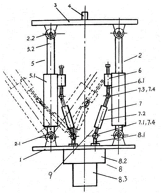
[0117] Example 1 ( figure 1 ) is an example of synchronous motion of moving pairs realized by mechanical transmission. It is a novel parallelogram complex kinematic pair [2RPR] composed of 2 RPR side chains 2. It consists of a frame 1, an output member 3, two RPR side chains 2 and a set of synchronous transmissions 9. The frame 1 and the output member 3 are parallel to each other, the axes of the side chains 2 are parallel to each other, and the axes of the respective rotating pairs of the rotating kinematic pairs are correspondingly parallel. The side chain 2 is composed of a frame rotation kinematic pair (rotation pair) 2.1 at the lower end, a moving pair 5, and an output component rotation kinematic pair 2.2; wherein the moving pair 5 is two electric cylinders. The motor 8.3 of the electric cylinder is separated from the mobile auxiliary cylinder body 5.1. The synchronous transmission device 9 includes a cylinder block connection transmission box 6 , a flexible shaft 7 ...

Embodiment 2

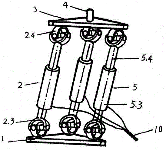
[0120] Example 2 ( figure 2 ) is a novel parallelogram complex kinematic pair [3UPU] composed of 3 UPU side chains 2, which has 3 degrees of freedom of movement. It includes a frame 1, a side chain 2, an output member 3 and a synchronous transmission 9. The side chain 2 is composed of the frame rotation type kinematic pair (Hooke hinge) 2.3 at the lower end, the moving pair 5, and the output member rotation type kinematic pair (Hooke hinge) 2.4 at the upper end point. The figure formed by the three fulcrums of the frame 1 is an equilateral triangle, and the figure formed by the three fulcrums of the output member 3 is also an equilateral triangle, which is congruent with the equilateral triangle of the output member 3 . Frame rotation kinematic pair 2.3 is a Hooke hinge, output member rotation kinematic pair 2.4 is a Hooke hinge, and the moving pair 5 is three identical linear servo electric cylinders: including the moving pair cylinder body 5.3 and the moving pair servo cylin...

Embodiment 3

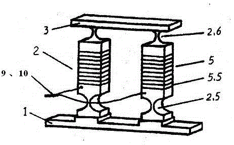
[0122] Example 3 ( image 3 ) is a new type of complex kinematic pair [2RPS] composed of two RPS side chains 2, which has two degrees of freedom for movement and one degree of freedom for rotation. It includes a frame 1, a side chain 2, an output member 3 and a synchronous transmission 9. The side chain 2 includes a frame rotation type kinematic pair (rotation pair) 2.5, a moving pair 5, and an output component rotation type kinematic pair (spherical joint) 2.6. The frame rotation kinematic pair 2.5 on frame 1 is a flexible (compliant) rotation pair, the output member rotation kinematic pair 2.6 of the output member 3 is a flexible ball pair (or flexible Hooke hinge), and the moving pair 5 is two identical A miniature mobile pair composed of the mobile auxiliary cylinder body 5.5 (laminated piezoelectric ceramic device). Both the frame 1 and the output member 3 are rectilinear. The synchronous transmission device 9 includes a computer system, a sensor, a signal output syste...


PUM


Abstract

The invention discloses a multi-translational-degree-of-freedom parallelogram complex kinematic pair. The multi-translational-degree-of-freedom parallelogram complex kinematic pair comprises a machine frame, an output member, side chains and synchronous transmitting devices. The machine frame is connected with the output member through the two or more side chains to form a whole, a kinematic pair body formed by connecting the side chains with the machine frame is a rotary type kinematic pair body, a kinematic pair body formed by connecting the side chains with the output member is also a rotary type kinematic pair body, the machine frame is parallel to the output member, the axes of the side chains are parallel, related rotary pair main bodies of the rotary type kinematic pair bodies are correspondingly parallel, a generalized prismatic pair is connected between the two end point kinematic pair main bodies of each side chain in series, and the synchronous transmitting devices are connected between at least two or three of the generalized prismatic pairs. The multi-translational-degree-of-freedom parallelogram complex kinematic pair has the multiple translational degrees of freedom, can be conveniently used as a driving pair and is a basic kinematic pair which is simple in function, short in force transmitting line and high in universality, brings convenience to standardization and can be independently used.

Description

Technical field: [0001] The invention relates to a robot kinematic pair, in particular discloses a parallelogram complex kinematic pair with multi-translation degrees of freedom, and also provides two robots made by using the kinematic pair, which belongs to the technical field of robot mechanisms. technical background: [0002] Existing kinematic pairs include two types of kinematic pairs, that is, rotational kinematic pairs and translational kinematic pairs. [0003] Existing rotary kinematic pairs include rotary joints, Hooke hinges, spherical joints and helical joints. The revolving pair has a rotational degree of freedom, hereinafter R is used to represent the revolving pair, referred to as the R pair; when the helical pair is used as a revolving pair, it also has a rotational degree of freedom, and the following H is used to represent the helical pair, referred to as the H pair, which is used as a revolving pair The helical pair is represented by the symbol Hr; the ...

Claims


Application Information

Patent Timeline
Patent Type & Authority Applications(China)
IPC IPC(8): B25J11/00
Inventor 韩方元
Owner 韩方元
Why Eureka
Try Eureka