
Method for determining equivalent engineering constants in planes of compound materials in thickness direction

A technology of composite materials and engineering constants, which is used in electrical digital data processing, special data processing applications, instruments, etc., and can solve problems such as limiting the application of two-dimensional finite element analysis of mechanical responses.

Inactive Publication Date: 2013-10-02
BEIHANG UNIV
View PDF1 Cites 13 Cited by
  • Summary
  • Abstract
  • Description
  • Claims
  • Application Information

AI Technical Summary

Problems solved by technology

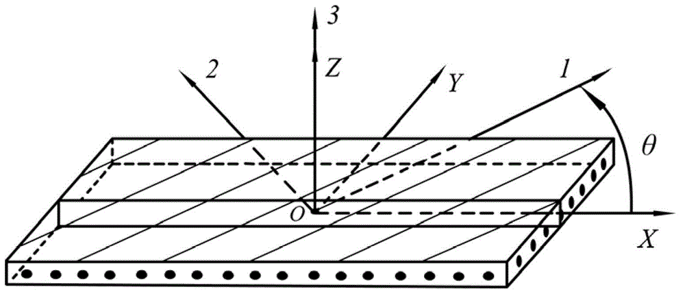
However, since the engineering constants of a single layer of composite material given in engineering reflect the material properties of the single layer in the direction of the three coordinate axes of the positive axis coordinate system, and the general layup angle of the single layer of composite material is in the plane of its thickness direction The material properties of the material cannot be directly determined by the engineering constants given in the engineering, which greatly limits the application of the two-dimensional finite element analysis in solving the mechanical response of the composite material structure in the thickness direction of the single layer.

Method used


Image

  • Method for determining equivalent engineering constants in planes of compound materials in thickness direction
  • Method for determining equivalent engineering constants in planes of compound materials in thickness direction
  • Method for determining equivalent engineering constants in planes of compound materials in thickness direction

Examples


Embodiment

[0052] Example: Shear Stress Analysis of the Middle Surface of the Adhesive Layer of a Composite Single Lap Bonded Joint Subjected to a Tensile Load

[0053] 1. Geometric description;

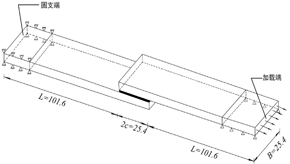
[0054] Such as image 3 As shown, the composite material single-lap adhesive joint to be studied is composed of two identical upper and lower lap plates and an intermediate adhesive layer. The transverse dimension of the joint is: B=25.4mm. The overlapping board is made of composite material laminated board, the length L is 101.6mm, the height h is 2mm, and the length 2c of the glued part is 25.4mm.

[0055] (1) The upper and lower composite material lap plates:

[0056] Lap-up form of lap joint board is [0 / 45 / -45 / 0] s , the thickness of each composite single layer is 0.25mm;

[0057] (2) Adhesive layer material:

[0058] The thickness of the glue layer is 0.13mm;

[0059] (3) Loads and boundary conditions:

[0060] The lower lap plate on the left side of the joint is fixed with a 20mm l...


PUM


Abstract

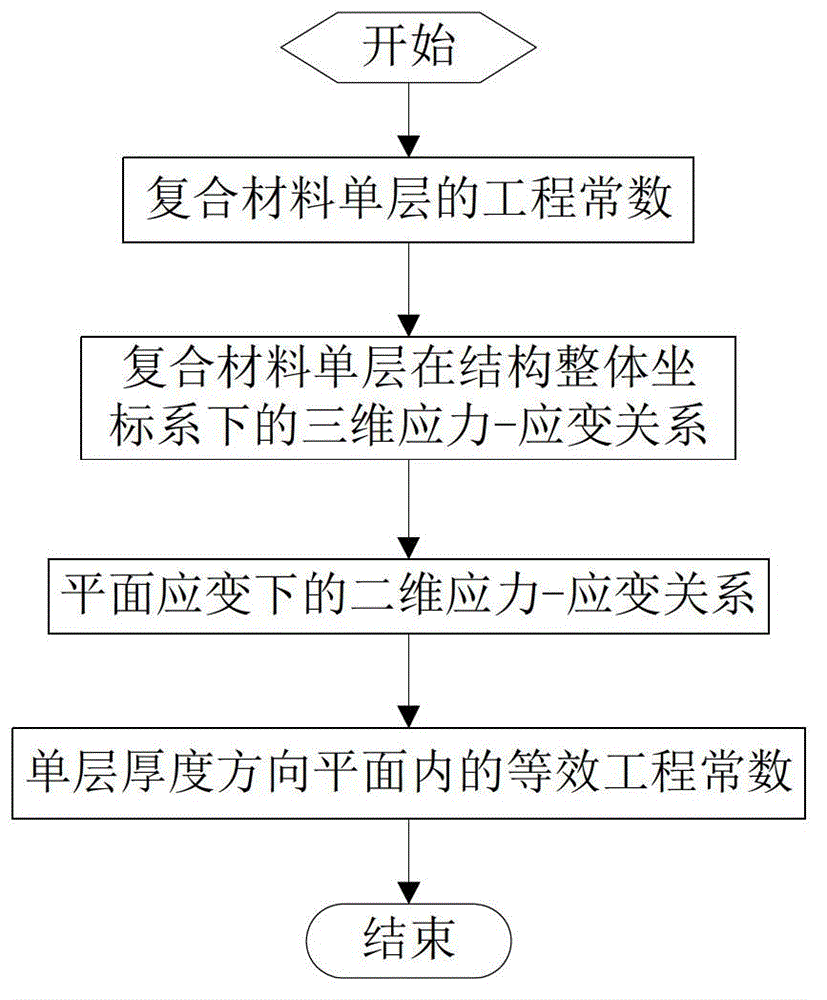
A method for determining equivalent engineering constants in planes of compound materials in the thickness direction includes a first step of determining a three-dimensional stress-strain relation of compound material single layers under a structural overall coordinate system, a second step of determining a two-dimensional stress-strain relation of the compound material single layers in the planes based on the three-dimensional stress-strain relation of the compound material single layers under the structural overall coordinate system according to a plane strain hypothesis in the planes of the compound material single layers in the thickness direction, and a third step of determining the equivalent engineering constants in the planes of the compound material single layers in the thickness direction. The method determines the equivalent engineering constants in the planes of the compound materials in the thickness direction, and the equivalent engineering constants can be directly input into commercial finite element software to endow material properties on each compound material single layer, and the method can be used for building a two-dimensional finite element model of each compound material single layer to solve mechanical response of a compound material structure. The method is favorable for improving analysis precision of the compound material structure and remarkably reducing calculation scales and cost, and has important engineering application value.

Description

technical field [0001] The invention belongs to the technical field of composite material structure design and analysis, and is a method for determining equivalent engineering constants in a plane in the thickness direction of composite materials. The equivalent engineering constants can be directly input into finite element software to assign material properties to each composite material single layer , to establish a two-dimensional finite element model of each composite material single layer, so as to establish an overall two-dimensional finite element model of the composite material structure, and solve the mechanical response of the composite material structure in the plane of the thickness direction of the single layer, so as to significantly reduce the Scale and Cost of Structural Computational Analysis. Background technique [0002] Compared with traditional materials, composite materials have the advantages of high specific strength, high specific modulus, light wei...

Claims


Application Information

Patent Timeline
IPC IPC(8): G06F17/50
Inventor 赵丽滨王雅娜陈玉丽
Owner BEIHANG UNIV
Learn More