Circuit, method and related device for preventing channel disturbance

A channel interference and circuit technology, applied in the field of communication, can solve problems such as handover failure, WiFi channel interference, etc.

Active Publication Date: 2015-03-25
HUAWEI DEVICE CO LTD
View PDF3 Cites 12 Cited by
  • Summary
  • Abstract
  • Description
  • Claims
  • Application Information

AI Technical Summary

Problems solved by technology

[0007] The embodiment of the present invention provides a circuit, method and related device for avoiding channel interference, which are used to solve the handover failure that may occur when the existing Mobile WiFi terminal switches between 2.4G WiFi and WiMAX (or LTE) systems, and the uplink WAN Mutual interference between the WiMAX (or LTE) system channel on the LAN side and the WiFi channel on the downlink LAN side

Method used


Image

  • Circuit, method and related device for preventing channel disturbance
  • Circuit, method and related device for preventing channel disturbance
  • Circuit, method and related device for preventing channel disturbance

Examples


Embodiment 1

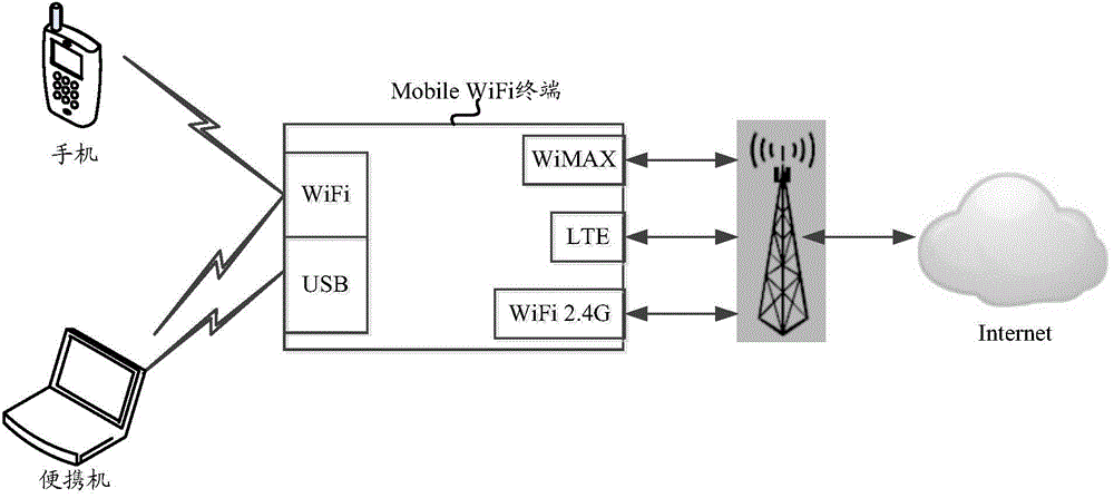
[0140] In the first embodiment, assuming that the Mobile WiFi terminal may exist in an environment where LTE system signals and WiFi signals in the LTE B41 (2625MHz-2655MHz) frequency band coexist, then according to the same inventive concept as the circuit provided by the embodiment of the present invention, the Mobile The circuit structure in the WiFi terminal can be as follows Figure 7 shown.

[0141] Figure 7 In , the arrow direction of the line segment indicates the flow direction of the signal, the arrow pointing to the WiFi chip indicates the flow direction of the signal received by the WiFi chip, and the arrow away from the WiFi chip indicates the flow direction of the signal transmitted by the WiFi chip. The meanings of the arrow directions of the line segments in the accompanying drawings are the same as Figure 7 The direction of the arrow in the middle line segment has the same meaning, which will not be repeated hereafter.

[0142] Figure 7 The shown antenn...

Embodiment 2

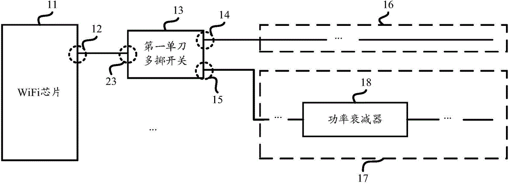
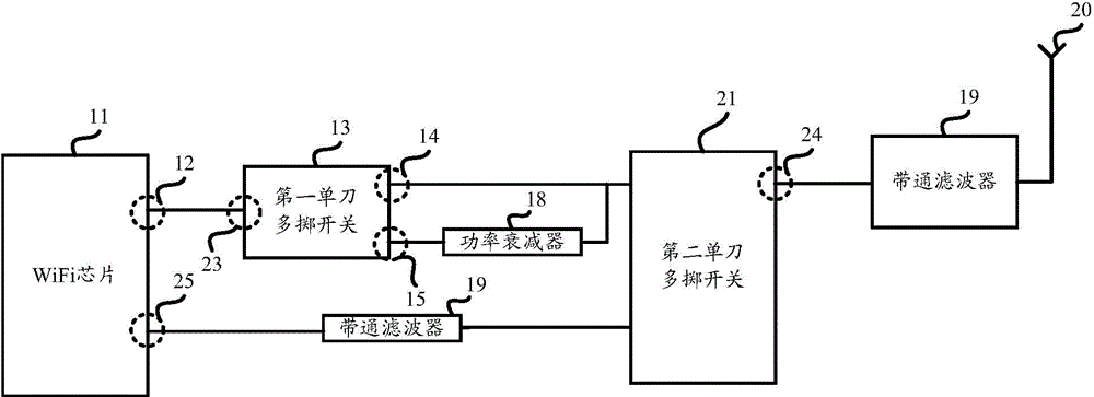
[0148] In the second embodiment, the circuit structure in the Mobile WiFi terminal is as follows Figure 9 shown. Based on this circuit structure, the signal transmitted by the signal signal transmitting pin (not marked in the figure) of the WiFi chip will be sent to the SPDT at first; then, the Mobile WiFi terminal (or AP) can control the SPDT to make The signal is sent to the П-type attenuator (referred to as П-attenuation) to attenuate the transmission power, and then enters another SPDT. After that, the attenuated signal enters the SPDT in the signal receiving branch, and then passes through the antenna. emission. Or, the Mobile WiFi terminal (or AP) controls the SPDT so that the signal directly enters the other SPDT mentioned above without attenuating the transmission power of the signal, and then enters the signal receiving branch. After the SPDT in the road, transmit through the antenna.

[0149] From the above description, it can be seen that between the SPDT connec...

Embodiment 3

[0153] In the third embodiment, the circuit structure in the Mobile WiFi terminal is as follows Figure 11 shown. Based on this circuit structure, the signal transmitted by the signal signal transmitting pin (not marked in the figure) of the WiFi chip will be sent to the SPDT at first; then, the Mobile WiFi terminal (or AP) can control the SPDT to make The signal is sent to a П-type attenuator (referred to as П-attenuator) to attenuate the transmission power, and then enters a single-pole three-throw switch SP3T, and then transmits through the antenna. Wherein, the SP3T is also in the signal receiving branch at the same time. Alternatively, the Mobile WiFi terminal (or AP) controls the SPDT so that the signal directly enters the above SP3T without attenuating the transmission power of the signal, and then transmits it through the antenna.

[0154] Regarding the first signal transmission branch and the second signal transmission branch existing between the SPDT and the antenn...


PUM


Abstract

The invention discloses a circuit, a method and a related device for preventing channel disturbance. The circuit comprises a wireless fidelity (WiFi) chip, and at least a first single pole multithrow switch, wherein the moving end of the first single pole multithrow switch is connected with a signal transmitting tube pin of the WiFi chip, the firs single pole multithrow switch comprises at least two immovable ends, a first immovable end of the two is connected with a first signal transmitting branch, a second immovable end of the two is connected with a second signal transmitting branch, the second signal transmitting branch comprises a power attenuator, the input end of the power attenuator is connected with the second immovable end of the first single pole multithrow switch, after the WiFi chip confirms that a first channel and a second channel mutually interfere, the WiFi chip controls the moving end of the first single pole multithrow switch to be connected with the second immovable end of the first single pole multithrow switch, wherein the first channel is a wireless local area network channel, and the second channel is different from the wireless local area network channel.

Description

technical field [0001] The present invention relates to the field of communication technology, in particular to a circuit, method and related device for avoiding channel interference. Background technique [0002] As the terminal currently supports more and more communication systems and signal frequency bands, it is becoming more and more easy for the terminal to face the problem of coexistence and mutual interference between signals of different communication systems that are sent and received by the terminal. Taking Wireless Fidelity (Wireless Fidelity, WiFi) and Long Term Evolution (LTE) systems as examples, since the LTE system has many application frequency bands, and there are many frequency bands that are relatively close to the frequency bands of WiFi, the current common differences A typical scenario of signal coexistence of communication standards is the coexistence of wireless local area network WiFi signals and LTE system signals. [0003] figure 1 It is a spe...

Claims


Application Information

Patent Timeline
Patent Type & Authority Applications(China)
IPC IPC(8): H04W24/02
CPCH04W24/02H04B17/345H04W48/06H04W48/18H04W84/04H04W84/12H04W88/06
Inventor 赵宇陈崇录陈栋张晓峰相超温小雨
Owner HUAWEI DEVICE CO LTD
Why Eureka
Try Eureka