Voltage-reduction structure LED driving circuit, and constant current driver and design method thereof

A technology of LED driving and constant current, applied in the direction of electric lamp circuit layout, instrument, electric light source, etc., can solve the problems of unfavorable circuit miniaturization, large volume of inductance L1, and increased cost.

Active Publication Date: 2015-03-25
HANGZHOU SILAN MICROELECTRONICS
View PDF6 Cites 9 Cited by
  • Summary
  • Abstract
  • Description
  • Claims
  • Application Information

AI Technical Summary

Problems solved by technology

In this case, in order to control the conduction time from being too small, the inductance of the inductor L1 is generally required to be large enough, otherwise the circuit will not work normally, and the volume of the inductor L1 will become very large at this time, resulting in an increase in cost. high, which is not conducive to the miniaturization of the circuit

Method used


Image

  • Voltage-reduction structure LED driving circuit, and constant current driver and design method thereof
  • Voltage-reduction structure LED driving circuit, and constant current driver and design method thereof
  • Voltage-reduction structure LED driving circuit, and constant current driver and design method thereof

Examples


no. 1 example

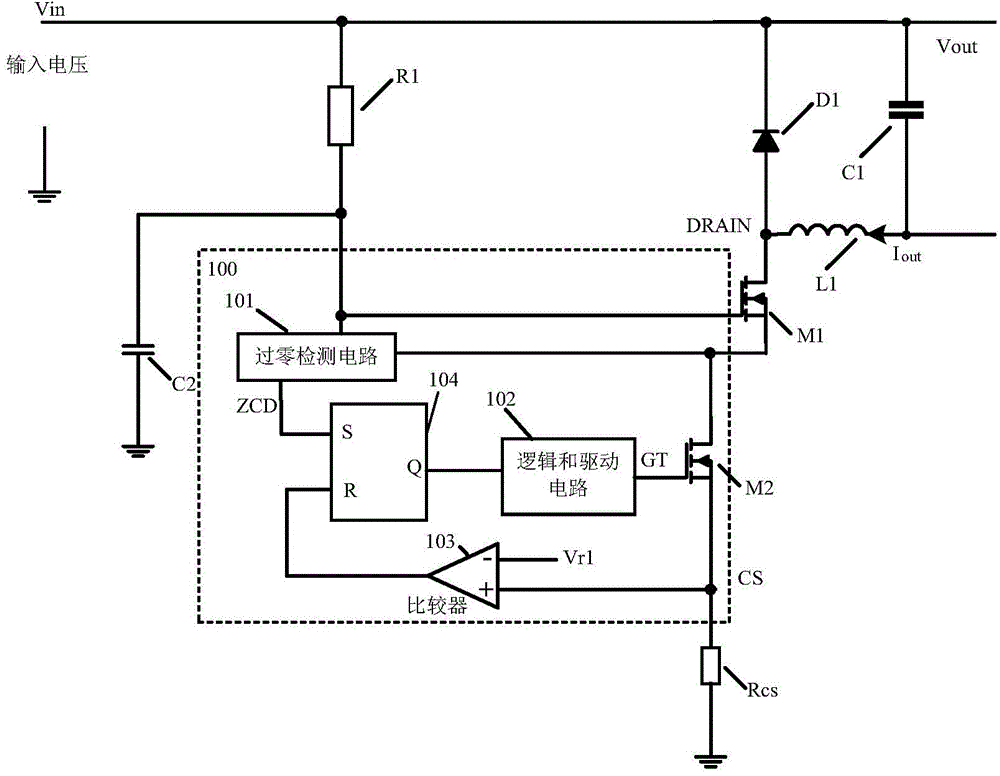
[0116] refer to figure 2 , The step-down structure LED driving circuit of the first embodiment includes: an input resistor R1 , an input capacitor C2 , a freewheeling diode D1 , a load capacitor C1 , an inductor L1 , a sampling resistor Rcs and a constant current driver 200 . Wherein, the constant current driver includes: a power switch, which may include a power tube M1 and a power tube M2; a zero-crossing detection circuit 201; a peak current comparator circuit 203; an opening signal generation circuit 205; a driving circuit 210, the driving circuit 210 RS flip-flop 204 and logic and drive circuit 202 may be included.

[0117] Among them, the first end of the input resistor R1 is connected to the input voltage input terminal Vin; the first end of the input capacitor C2 is connected to the second end of the input resistor R1, and its second end is grounded; the cathode of the freewheeling diode D1 is connected to the input voltage input terminal. Terminal Vin; the first end...

no. 2 example

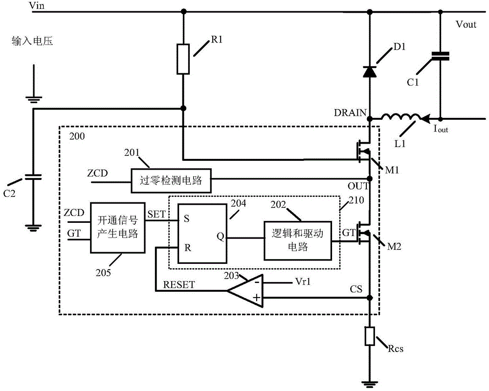
[0136] refer to Figure 7 , Figure 7 The buck structure LED driver circuit shown in the second embodiment with figure 2 Basically the same, the difference is that the power switch of the second embodiment only includes the power transistor M3, the drain terminal of which is connected to the first terminal of the inductor L1, the gate terminal of which receives the driving signal GT, and the source terminal of which is grounded through the sampling resistor Rcs. The connection structures and working principles of other components in the second embodiment are the same as those in the first embodiment, and will not be repeated here.

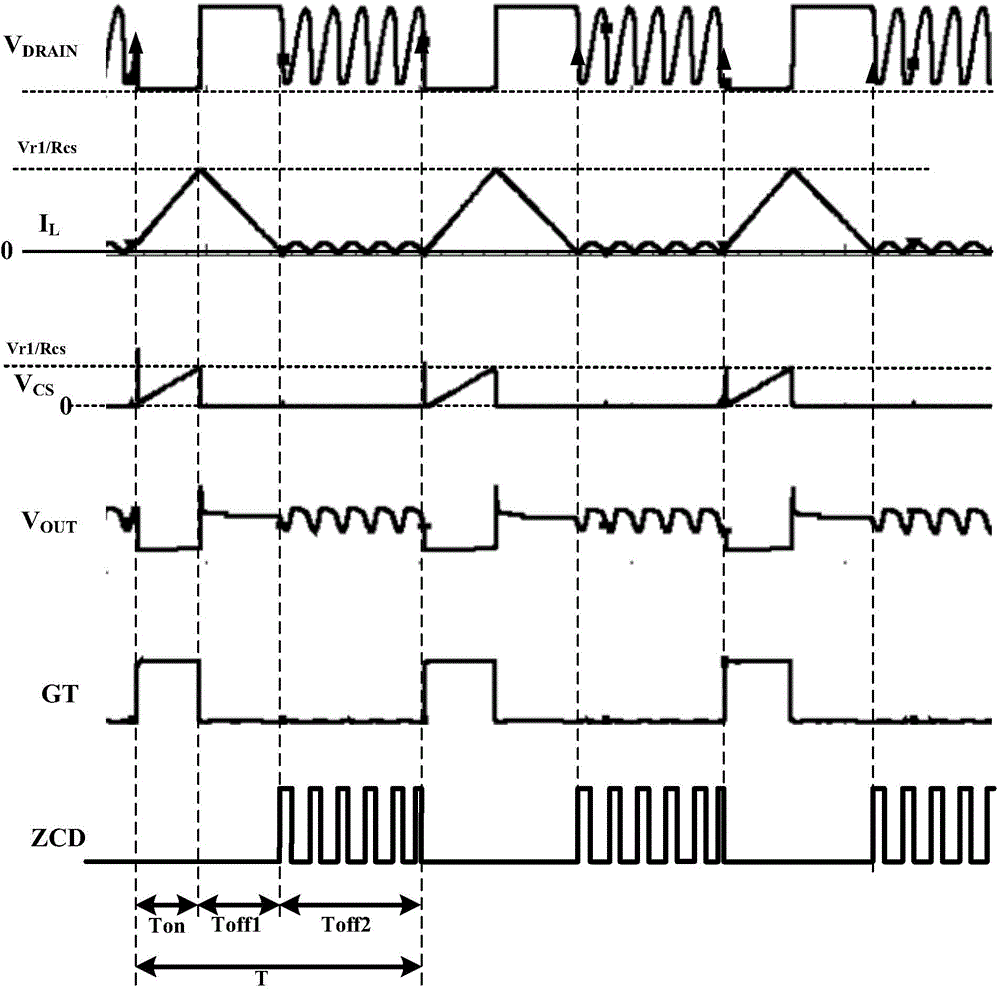
[0137] To sum up, the present invention provides a LED drive circuit with a step-down structure and its constant current driver, which uses the peak current of the inductor to control the turn-on time of the power switch, uses the turn-on signal generating circuit to determine the turn-off time of the power switch, and turns on the signal generat...


PUM


Abstract

The invention provides a voltage-reduction structure LED driving circuit, and a constant current driver and a design method of the voltage-reduction structure LED driving circuit. The driver comprises a power switch, a zero cross detection circuit, an on-signal generation circuit and a driving circuit, wherein the power switch is directly or indirectly connected with an inductor in the voltage-reduction structure LED driving circuit, the zero cross detection circuit responds to inductor current and outputs a zero cross detection signal in a zero cross mode, the on-signal generation circuit obtains inductor current duration time according to a driving signal and the zero cross detection signal, determines the inductor current interruption time according to the inductor current duration time and generates a setting signal used for switching on of the power switch so that the ratio from the inductor current duration time to the inductor current interruption time can be kept as a preset value, and the driving circuit is used for generating the driving signal according to a resetting signal for switching off the power switch and the setting signal. Under the condition of the same output current, the peak current of the inductor is increased, the inductance amount of the inductor is reduced, and the driver is particularly suitable for occasions with low output current and low requirement for the inductance amount.

Description

technical field [0001] The invention relates to switching power supply technology, in particular to a LED driving circuit with a step-down structure, a constant current driver and a design method thereof. Background technique [0002] refer to figure 1 , figure 1 It shows a traditional source-driven step-down structure LED drive circuit, which mainly includes: input resistor R1, input capacitor C2, freewheeling diode D1, output load capacitor C1, inductor L1, first power switch M1, sampling resistor Rcs and a constant current driver 100 , wherein the constant current driver 100 includes a second power switch M2 , a zero-crossing detection circuit 101 , a logic sum drive circuit 102 , a comparator circuit 103 and an RS flip-flop 104 . When the first power switch M1 is turned on, the second power switch M2 is also turned on, and the input current flows through the output load capacitor C1, the output terminal Vout, the inductor L1, the first power switch M1, the second power...

Claims


Application Information

Patent Timeline
Patent Type & Authority Applications(China)
IPC IPC(8): H05B37/02H02M3/156H02M1/36
CPCY02B20/40
Inventor 姚云龙
Owner HANGZHOU SILAN MICROELECTRONICS
Why Eureka
Try Eureka