SEPIC feed buck-boost converter

A buck-boost converter and power feeding technology, which is applied in the direction of high-efficiency power electronic conversion, no intermediate conversion to AC conversion equipment, DC power input conversion to DC power output, etc., can solve the problem of large output ripple and limit application and promotion , Converter drive logic complexity and other problems, to reduce input current/voltage ripple, suppress switch resonance phenomenon, reduce output EMI effect

Active Publication Date: 2015-06-24
STATE GRID CORP OF CHINA +1
View PDF5 Cites 8 Cited by
  • Summary
  • Abstract
  • Description
  • Claims
  • Application Information

AI Technical Summary

Problems solved by technology

[0003] In the application of conventional buck-boost DC-DC converters, the four-switch Buck-Boost converter is more common. It uses a shared energy storage inductance to couple the Buck topology and the Boost topology, and realizes the conversion through the front-stage step-down + post-stage boost structure. The buck-boost function of the converter, but its reserved four-switch structure makes the drive logic of the converter more complicated, and the output ripple is large when the input and output voltages are close, and the boost working mode and the buck working mode cannot be realized smooth switching; in addition, the two-stage coupled inductance with large inductance also reduces the dynamic response performance of the converter
For classic Buck-Boost converters such as polarity inversion converters and SEPIC converters, although their driving logic is relatively simple, they can only work in asynchronous switching mode, and the output diodes reduce the working efficiency of the converters, and also Limit their application promotion
[0004] To sum up, although the traditional buck-boost converter can realize the basic buck-boost conversion function, it still needs to be improved and improved in terms of topology work efficiency, dynamic response performance, and drive logic control.

Method used

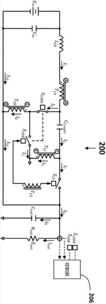
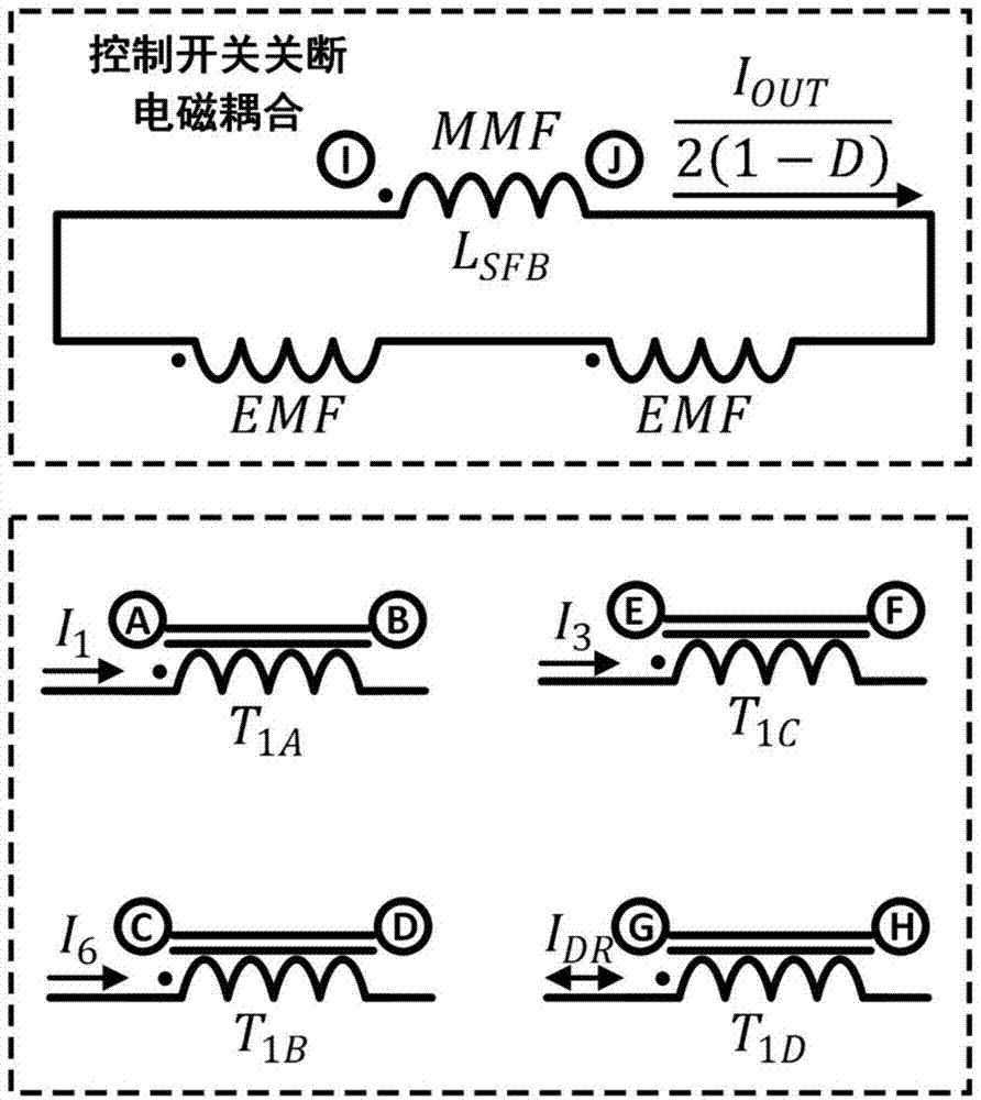
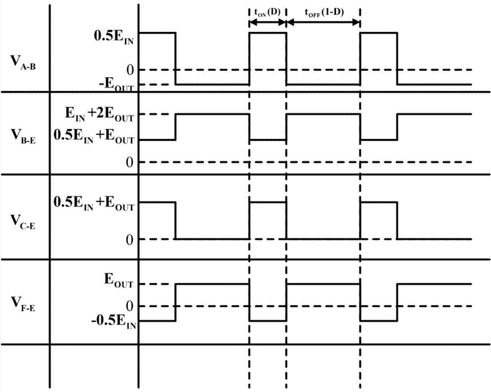

Image

  • SEPIC feed buck-boost converter
  • SEPIC feed buck-boost converter
  • SEPIC feed buck-boost converter

Examples


Embodiment Construction

[0036] The present invention will be further described below in conjunction with the accompanying drawings and embodiments.

[0037] The following description is not intended to be limiting, but merely for the purpose of describing the general principles of the exemplary embodiments. The scope of the present invention should be determined with reference to the claims.

[0038] In the following description, numerous specific details are set forth in order to provide a thorough understanding of the present invention. However, those of ordinary skill in the art need not be employed in the specific details to practice the present invention. In other instances, well-known materials or methods have not been described in detail to avoid obscuring the present invention.

[0039] References throughout this specification to "one embodiment," "an embodiment," "an example," or "an example" mean that a specific feature, structure, or characteristic described in connection with the embodi...


PUM


Abstract

The invention discloses an SEPIC feed buck-boost converter comprising an SEPIC circuit, a polarity inversion converting circuit and a controller which are mutually coupled. The SEPIC circuit is connected with a power source. The SEPIC circuit and the polarity inversion converting circuit are connected through a control switch. The polarity inversion converting circuit is connected with a load. When the control switch SISBB is closed, the SPPIC circuit stores the electric energy of the power source in an energy storing coupled inductor of the SEPIC circuit and the polarity inversion converting circuit; meanwhile, an energy storage coupled capacitor feeds back electric energy to the load through the polarity inversion converting circuit. When the control switch is switched off, the power source feeds back electric energy to the load through the SEPIC circuit, and electric energy is fed back to the load by the energy storing coupled inductor of the SEPIC circuit and the polarity inversion converting circuit through the SEPIC circuit and the polarity inversion converting circuit. By the adoption of the SEPIC feed buck-boost converter, the work efficiency of the converter is improved, output follow current of the converter can be achieved, and the output EMI of the converter is reduced.

Description

technical field [0001] The invention relates to a SEPIC feeding buck-boost converter. Background technique [0002] At present, new energy power generation is widely used in small and medium power distributed power generation occasions such as household combined heat and power systems. It is usually composed of fuel cells, photovoltaic cells, lithium batteries and other new energy cells connected in series and parallel to increase output. voltage and output current to meet the power demand of the load. The output characteristics of the above-mentioned new energy power generation systems usually have the following characteristics: first, the output voltage is relatively low, and may fall within the input demand voltage range of the subsequent DC load or cascaded inverter device; second, the output voltage characteristics are relatively soft, namely , the voltage variation range between no-load and full power output is large. Therefore, it is hoped that the cascaded converte...

Claims


Application Information

Patent Timeline
Patent Type & Authority Applications(China)
IPC IPC(8): H02M3/07H02M1/14H02M1/44
CPCH02M1/14H02M3/155H02M1/0058H02M3/1557Y02B70/10
Inventor 彭飞陈玉峰辜超朱文兵周加斌朱孟照杜修明朱庆东王建任敬国李杰白德盟
Owner STATE GRID CORP OF CHINA
Why Eureka
Try Eureka