Cash gate self-locking mechanism

A banknote door and self-locking technology, applied in the field of purely mechanical banknote door self-locking mechanism, can solve problems such as potential safety hazards, and achieve the effects of low cost, improved safety performance, and simple and smart structure

Active Publication Date: 2015-04-01
SHENZHEN YIHUA COMP +2
View PDF6 Cites 4 Cited by
  • Summary
  • Abstract
  • Description
  • Claims
  • Application Information

AI Technical Summary

Problems solved by technology

[0002] In the prior art, there is no cash door self-locking device in the receiving department of financial machines such as automatic teller machines. When the cash door is closed, it can still be opened artificially, and there is a certain potential safety hazard.

Method used


Image

  • Cash gate self-locking mechanism
  • Cash gate self-locking mechanism
  • Cash gate self-locking mechanism

Examples


Embodiment Construction

[0016] The present invention will be further described in detail below through specific embodiments in conjunction with the accompanying drawings.

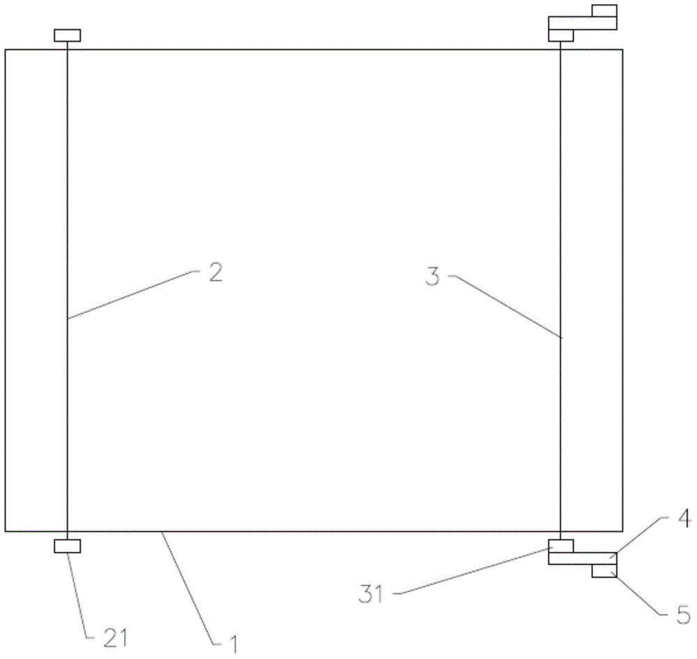
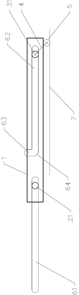
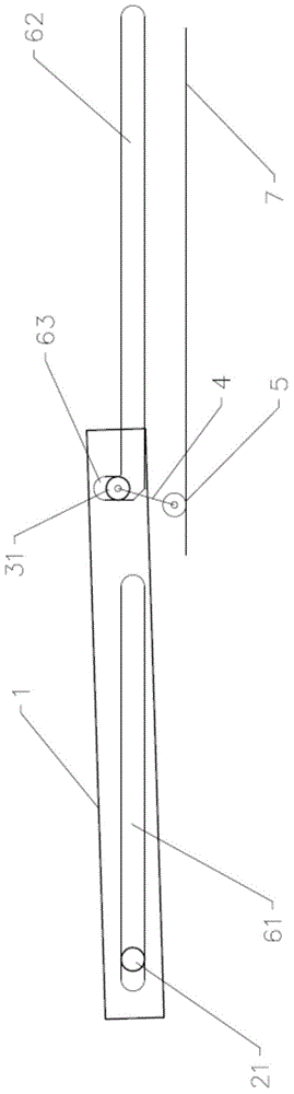
[0017] see figure 1 and figure 2 , one embodiment of the present invention provides a banknote door self-locking mechanism, including two banknote door front wheels 21 and two banknote door rear wheels 31 arranged on both sides of the banknote door 1, two banknote door front wheels 21 and two banknote door rear wheels 31 are arranged front and rear in sequence, the two banknote door front wheels 21 are connected by the front shaft 2 passing through the banknote door 1, and the two banknote door rear wheels 31 are connected by the rear axle 3 passing through the banknote door 1. Both sides of the banknote door 1 are respectively provided with elongated first guide grooves 62 corresponding to the movement track of the banknote door rear wheels 31, and the banknote door rear wheels 31 are placed in the first guide grooves 62 and ru...


PUM


Abstract

The invention provides a cash gate self-locking mechanism. Cash gate rear wheels are arranged at the two sides of a cash gate, respectively; strip-shaped first guide grooves are formed on the two sides of the cash gate to correspond to the movement locus of the corresponding cash ate rear wheels; the cash gate rear wheels are arranged in the first guide grooves and capable of sliding back and forth along the first guide grooves; the cash gate self-locking mechanism further comprises connecting rods and power wheels, as well as a power belt arranged in parallel to the first guide grooves, wherein each connecting rod is arranged correspondingly to each cash gate rear wheel and rotatably connected with the cash gate rear wheel and each power wheel is rotatably connected with the other end of the corresponding connecting rod; the power wheels are arranged on the power belt and move together with the power belt; a self-locking slot is formed at the position of each cash gate rear wheel after each first guide groove is completely closed correspondingly to the cash gate; the self-locking slot is a notch formed on one side of the first guide groove and capable of receiving the cash gate rear wheel. The cash gate self-locking mechanism is of a pure mechanical structure, and is simple in structure, good in self-locking effect and low in cost, and has an excellent self-locking effect.

Description

technical field [0001] The invention relates to a banknote door self-locking mechanism, in particular to a purely mechanical banknote door self-locking mechanism. Background technique [0002] The cash door self-locking device is not provided in the receiving section of financial machines and tools such as automatic deposit and teller machines in the prior art. When the cash door is closed, it can still be opened artificially, and there is a certain potential safety hazard. Contents of the invention [0003] The technical problem solved by the present invention is to provide a purely mechanical banknote door self-locking mechanism capable of realizing banknote door self-locking. [0004] The technical solution of the present invention to solve the above-mentioned technical problems is to provide a self-locking mechanism for the banknote door, the rear wheels of the banknote door are respectively arranged on both sides of the banknote door, and the two sides of the banknote...

Claims


Application Information

Patent Timeline
IPC IPC(8): G07F9/00
Inventor 吕响红
Owner SHENZHEN YIHUA COMP
Why Eureka
Try Eureka