Tool cutting edge wear detection fixture

A technology for detecting fixtures and cutting edges, which is applied to measuring devices, testing wear resistance, instruments, etc., can solve problems such as difficult accurate positioning and clamping, poor versatility, and complex structure, and achieves convenient positioning and clamping, compact structure, The effect of simple fixture structure

Active Publication Date: 2020-04-07
DALIAN UNIV OF TECH
View PDF7 Cites 0 Cited by
  • Summary
  • Abstract
  • Description
  • Claims
  • Application Information

AI Technical Summary

Problems solved by technology

[0004] The invention mainly solves the problems that the existing tool wear detection jig has poor versatility, complex structure and difficult to realize accurate positioning and clamping, and invents a tool cutting edge wear detection jig

Method used


Image

  • Tool cutting edge wear detection fixture
  • Tool cutting edge wear detection fixture
  • Tool cutting edge wear detection fixture

Examples


Embodiment Construction

[0015] The concrete implementation of the present invention is described in detail below in conjunction with accompanying drawing and technical scheme:

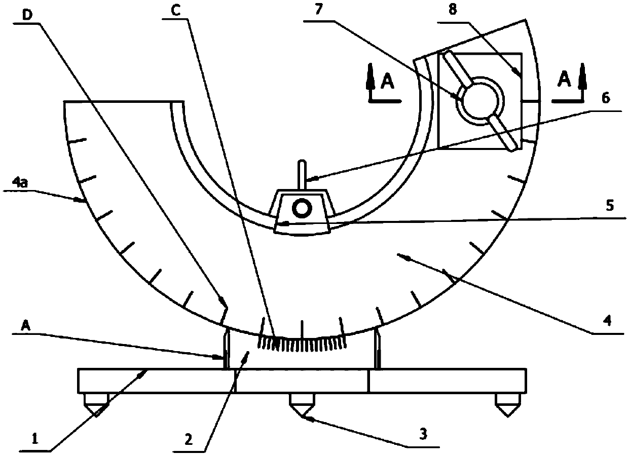
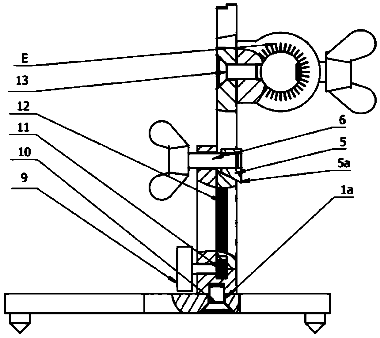
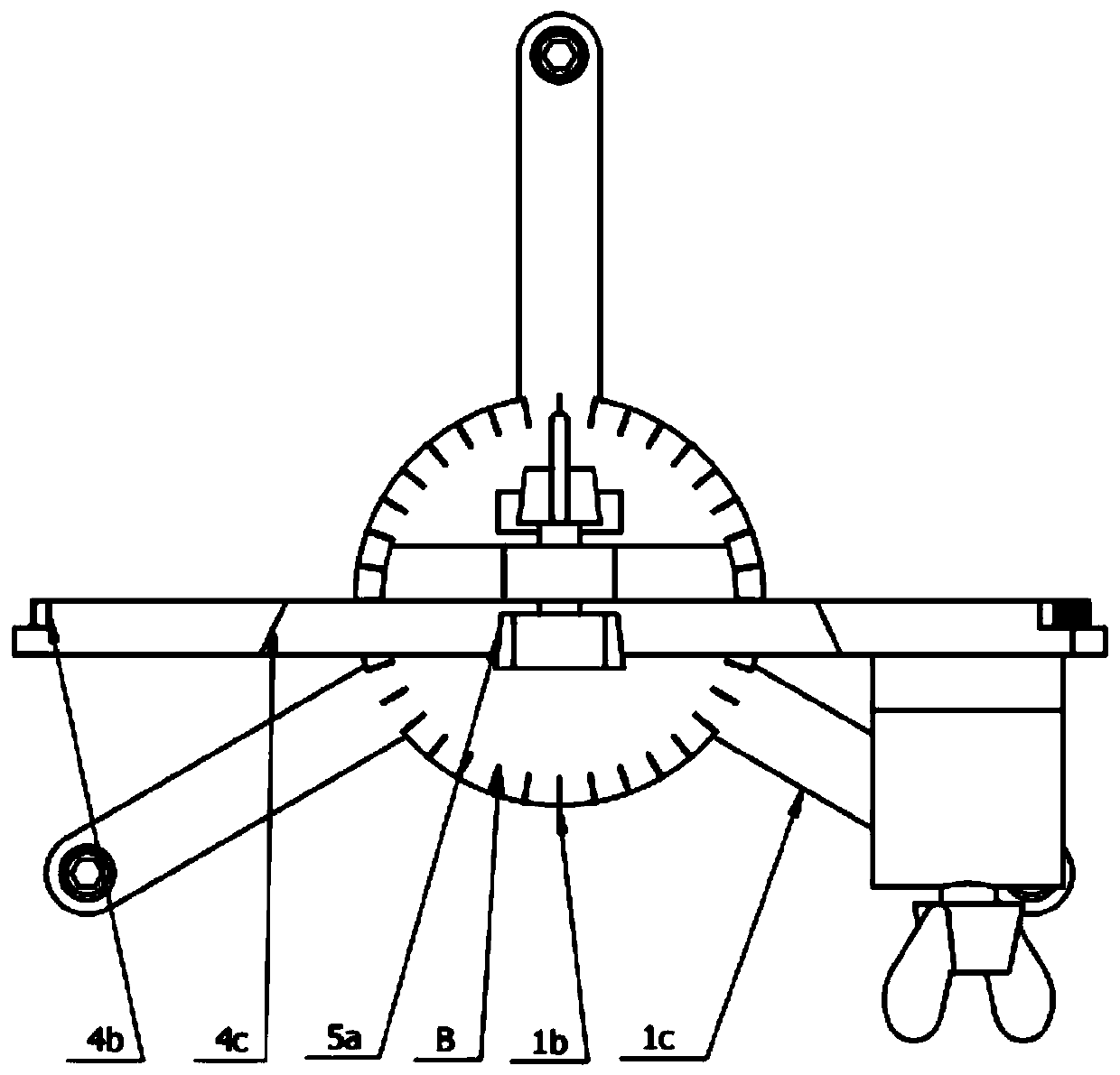
[0016] In the embodiment, the fixture is composed of a base, a bracket, an indexing plate, a gear assembly, a pressing assembly, and a cartridge assembly; the set of engraved lines for accurately indicating the circumferential rotation angle of the mechanism is engraved on the fixture, and the pitch angle of the tool is also engraved. Accurate positioning of the degree, the set of marking lines indicating the pitch angle of the indexing plate and the marking line of the chuck angle for positioning the knife with the accurate reading of the tool handle mark. The fixture has three rotational degrees of freedom and is a tool inspection fixture with scale indication and fastening functions, which can realize rapid and accurate positioning, locking and inspection of the tool, and improves the inspection efficiency and accuracy.

...


PUM


Abstract

The invention relates to a tool cutting edge wear detection clamp and belongs to the field of tool detection tools. The clamp is particularly suitable for detection of the cutting edge of a fiber reinforced composite hole drilling tool, and comprises a base, a bracket, an indexing disc, a gear assembly, a pressing assembly and a clamping cylinder assembly, wherein a scribed line group for accurately indicating the circumferential rotation angle of the clamp, a scribed line group for accurately positioning the degree of the pitching angle of a tool and indicating the pitching angle of the indexing disc and a clamping cylinder angle scribed line for accurate reading, positioning and tool setting in coordination with the mark of a tool handle are engraved on the clamp. The clamp is fastened by a fastening screw and a knob locking mechanism. The clamp is simple in structure, compact and smart, and parts are convenient to dismount, mount and clamp. The clamp is prevented from loosening andslipping in the measurement process, and tool detection efficiency and accuracy are improved.

Description

technical field [0001] The invention belongs to the field of tool detection tools, and relates to a tool cutting edge wear detection jig, which is especially suitable for detecting the cutting edge of a fiber reinforced composite material drilling hole making tool. Background technique [0002] Fiber-reinforced composite materials are widely used in many fields due to their light weight, high strength, corrosion resistance, and fatigue resistance. In order to meet the assembly requirements of composite components, a large number of drilling operations are required. However, its fiber-reinforced phase is highly abrasive, and it is easy to scratch the tool during drilling, resulting in rapid degradation of the cutting edge and reduced tool life. After the tool is worn out, it is not conducive to fiber cutting, affects the quality of the hole wall and causes damage such as delamination, tearing and burrs at the exit. In addition, the increased friction between the tool and the...

Claims


Application Information

Patent Timeline
Patent Type & Authority Patents(China)
IPC IPC(8): G01N3/04G01N3/56
Inventor 贾振元郝佳轩王福吉白玉高顿林马瑜成德
Owner DALIAN UNIV OF TECH
Why Eureka
Try Eureka