


Quick Research
Generate reliable direction feasibility study reports for your R&D in just a few steps.

Technical Q&A
Discover and master advanced knowledge NOW. Basics, ideas, possibilities, all at once.

Find Solutions
As an expert in R&D theories, this can generate solutions to your technical problems instantly.

Evaluate Feasibility
Analyze your overall solution with one click, know your potential R&D risks in advance.

Monitor Landscape
Get weekly tech updates, stay abreast of the latest tech innovations and key insights.
A fixed frame for easy adjustment of angle
A technology for adjusting the angle and fixing the frame, which is applied in the direction of selecting devices and electrical components, and can solve the problems of affecting the angle positioning of WLAN equipment, increasing the risk of installation work, and having many components in the installation structure, so as to achieve easy portability and placement, and safe operation. Strong performance and good versatility
- Summary
- Abstract
- Description
- Claims
- Application Information
AI Technical Summary
Problems solved by technology
Method used
Image

Examples
Embodiment 1
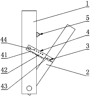
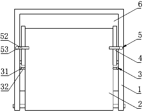
[0019] like Figure 1 to Figure 2 As shown, a fixed frame that is convenient for adjusting the angle includes a hollow connecting frame 1, a connecting plate 2 and a mounting plate 6, the mounting plate 6 is fixedly connected to the rear end of the connecting frame 1, and the mounting plate 6 and the connecting frame 1 jointly constitute The cavity that can accommodate the connecting plate 2, the lower end of the connecting plate 2 is hinged to the lower end of the connecting frame 1, and the two sides of the connecting plate 2 are provided with convex nails 3, and the convex nails 3 include a nail head 31 and a nail rod 32 whose diameter is smaller than that of the nail head 31 One end of the nail rod 32 is fixedly connected with the connecting plate 2, and the other end is fixedly connected with the nail head 31. The two sides of the connecting frame 1 are hinged with telescopic adjusting rods 4, and the adjusting rod 4 includes a first movable bar hinged with the connecting ...
Embodiment 2
[0023] This embodiment makes the following further limitations on the basis of Embodiment 1: the automatic clamping member 45 includes two oppositely arranged clamping components 46 with one end larger and one end smaller, and two clamping components 46 fixedly connected at both ends. The second elastic member 47, two clips 46 are arranged laterally in the second movable strip 43, the second movable strip 43 is provided with an opening 48 that can pass through the small end of the clip 46 and can hold the large end of the clip 46, the two clips The small ends of the clips 46 pass through the opening 48 . In this embodiment, the clip 46 may be in the shape of a hemisphere, a triangular piece, or the like. like Figure 4 As shown, the small ends of the two clips 46 extend out of the opening 48 under the support of the second elastic member 47 . When the small ends of the two clips 46 moved to the lock holes 44, the small ends of the two clips 46 passed through the lock holes 4...
Embodiment 3
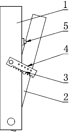
[0025]This embodiment makes the following further limitations on the basis of Embodiment 1: the connecting frame 1 is provided with a movable locking member 5 that can fix the connecting plate 2 in the cavity, such as Figure 5 As shown, the movable locking member 5 includes a positioning column 51 that can perform telescopic movement relative to the connecting frame 1 and a movable piece 52 that is sleeved on the positioning column 51 and can rotate along the axis of the positioning column 51. Fixedly connected with a spacer 54 whose diameter is greater than the diameter of the positioning column 51, the end face of the connecting frame 1 is provided with a first spacer groove that can be inserted into the spacer 54, and the bottom of the first spacer groove is provided with the lower end of the positioning column 51. The second limiting groove that matches and communicates with the first limiting groove, the lower end of the positioning column 51 is placed in the second limit...
PUM
 Abstract
Description
Claims
Application Information
 - R&D Engineer
- R&D Manager
- IP Professional
- Industry Leading Data Capabilities
- Powerful AI technology
- Patent DNA Extraction
Browse by: Latest US Patents, China's latest patents, Technical Efficacy Thesaurus, Application Domain, Technology Topic, Popular Technical Reports.
© 2024 PatSnap. All rights reserved.Legal|Privacy policy|Modern Slavery Act Transparency Statement|Sitemap|About US| Contact US: help@patsnap.com