
Non-repeated support continuous support advanced hydraulic support

A hydraulic support and support advanced technology, applied in the direction of mine roof support, mining equipment, earthwork drilling, etc., can solve the problems of roof damage, unsuitable roof, low efficiency, etc., to avoid the effect of repeated support

Active Publication Date: 2016-10-05
CHINA COAL BEIJING COAL MINING MACHINERY
View PDF6 Cites 0 Cited by
  • Summary
  • Abstract
  • Description
  • Claims
  • Application Information

AI Technical Summary

Problems solved by technology

Due to the queuing-type step-by-step moving method adopted by the large-scale advanced supports, it is inevitable to repeatedly support the roof, which is easy to cause damage to the roof and difficult to maintain, so it is impossible to realize the excavation of the stress-affected area along the groove (usually at 50 meters), all hydraulic supports are used for advance support. Beyond 20 meters for advance support, only relatively backward support methods such as multi-row single hydraulic props and shed beams can be used, which is not only inefficient, but also pedestrians and Operator safety is difficult to fully guarantee
In addition, the current advanced support is not suitable for roadways with broken roofs, coal roadways, and gob-side retaining roadways, etc., due to damage to the roof due to repeated support

Method used


Image

  • Non-repeated support continuous support advanced hydraulic support
  • Non-repeated support continuous support advanced hydraulic support
  • Non-repeated support continuous support advanced hydraulic support

Examples


specific Embodiment

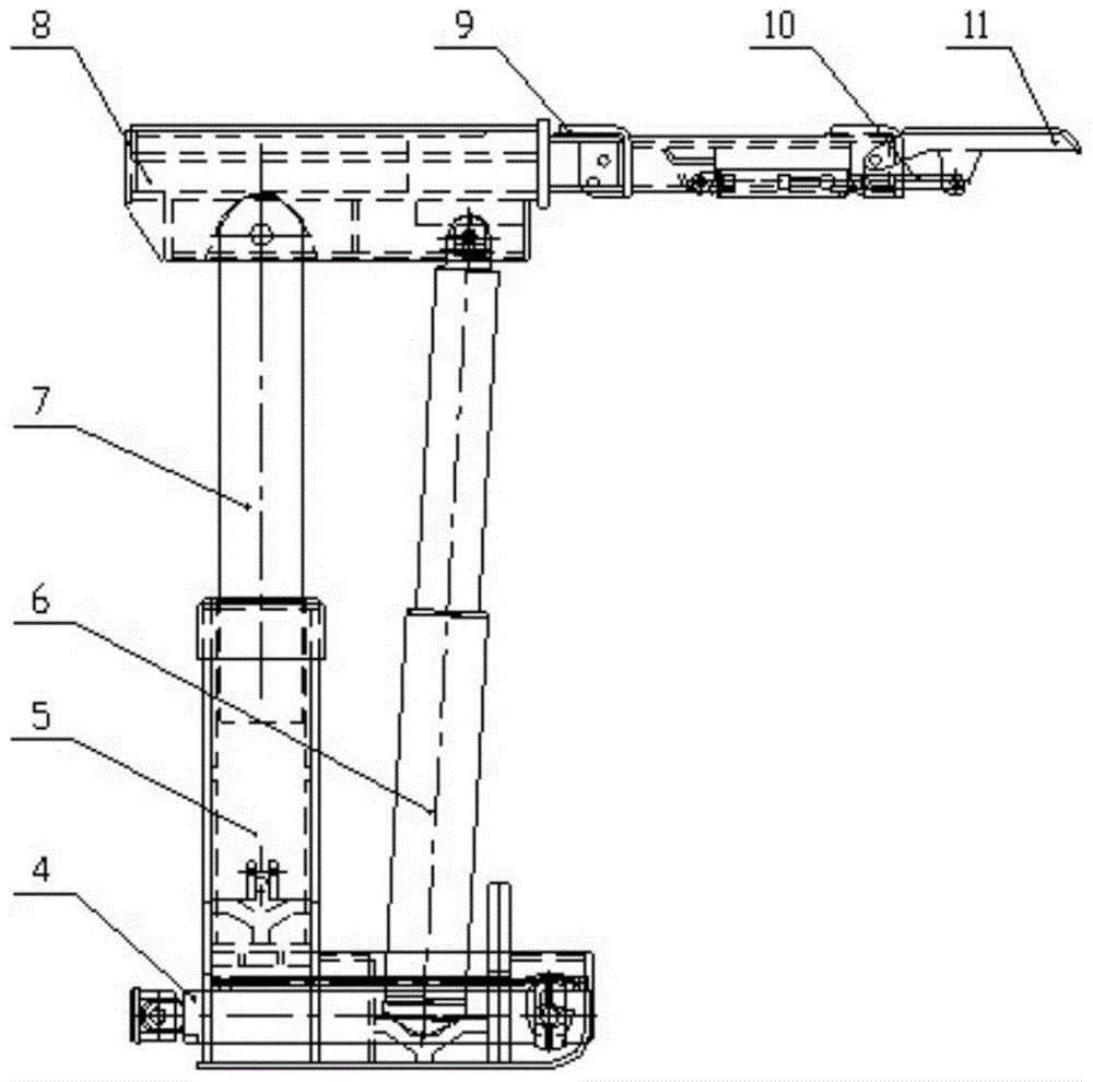
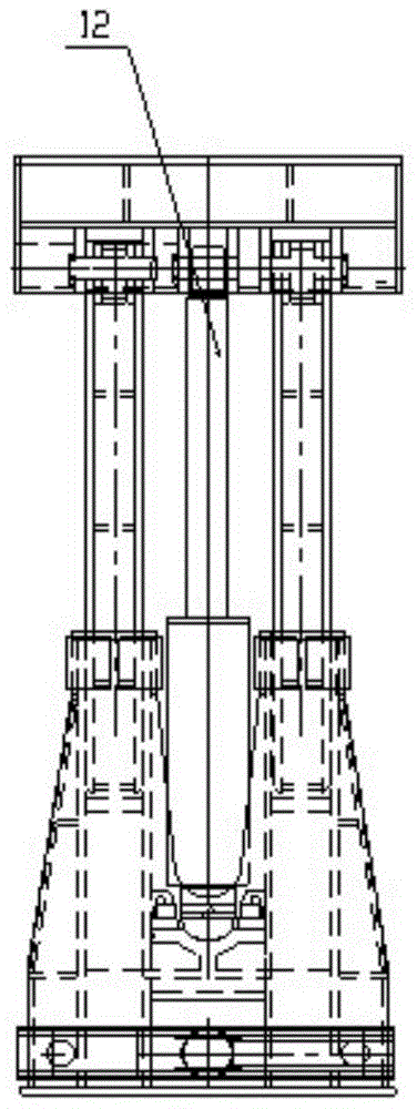
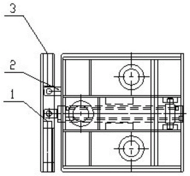
[0029] Such as Figure 1a , Figure 1b , Figure 1c As shown, it includes rotation lock pin 1, push beam fixed ear seat 2, push beam 3, push jack 4, base 5, column 6, telescopic rod 7, top beam 8, telescopic beam 9, side protection jack 10, side protection 11 , Balance jack 12.

[0030] The structural form is a telescopic rod-type stabilizing mechanism, a large balance jack, and a new type of two-column cover-type advanced hydraulic support without cover beams. The bracket has no movable side guards, long telescopic beams, and small side guard structures. Large support area, light weight, small transport size.

[0031] Such as figure 2 As shown, the top beam is a double-layer structure, the upper layer is a telescopic beam box, the lower layer is a column socket and box structure, and the telescopic beam jack and the side protection jack are placed in the middle layer.

[0032] The telescopic beam is in the form of a large beam head, and the installation position of the ...


PUM


Abstract

The invention discloses a repeated-support-free continuous support forepoling hydraulic support frame, which comprises a base and a top beam, wherein a telescopic rod is arranged at the back part of the base, the upper end of the telescopic rod is connected with the back part of the top beam, an upright post is arranged between the front part of the base and the front part of the top beam, the front part of the top beam is provided with a telescopic beam and a telescopic beam jack, the front part of the telescopic beam is provided with a protection upper and a protection upper jack, the back part of the base is provided with a pushing and moving cross beam, the pushing and moving cross beam is hinged to a pushing and moving beam fixing lug seat arranged on the base, a pushing and moving jack is connected between the pushing and moving cross beam and the base, one end of the pushing and moving cross beam is of a hollow structure, the other end of the pushing and moving cross beam is provided with a rotating lock pin, and the lower part of the telescopic beam is provided with an installation position of a monorail crane. The mode of the front support frame conversion according to the back support frame during the frame moving of the forepoling support frame can be realized, the repeated support on a roadway top plate is avoided, the general use of special-shaped roadways, rectangular roadways and different-width roadways of mechanically mining working faces can be realized, and the forepoling 50-meter fully mining influence region support can be realized.

Description

technical field [0001] The invention relates to an advanced hydraulic support for coal mines, in particular to an advanced hydraulic support for continuous support without repeated support. Background technique [0002] The support along the channel of the modern mechanized coal mining face is very important, which directly affects the coal mining operation, ventilation and safety of the working face. The geological conditions of the roadway are complex, and the horizontal stress and vertical stress distribution of the rock formation are different. The mining vibration of the working face of the tunnel roadway will increase the stress of the roadway, the roof will sink or fall off, and the two sides of the roadway will also shrink inward, which directly affects the coal mining operation. and personnel safety, especially about 50 meters in front of the fully mechanized mining face, affected by the stress concentration in front of the fully mechanized mining face, the roadway ...

Claims


Application Information

Patent Timeline
Patent Type & Authority Patents(China)
IPC IPC(8): E21D23/04
CPCE21D23/04E21D23/063
Inventor 孙如钢刘国柱钱洋喜包冬生张守祥吕金龙张亚龙
Owner CHINA COAL BEIJING COAL MINING MACHINERY
Learn More