a pinning mechanism

A technology of pin connection and rotation mechanism, applied in the direction of pivot connection, etc., can solve the problems of easy loss of pins, inconvenient operation, difficult insertion of pins, etc., and achieve the effect of ensuring two-way stop function, simple structure, and convenient installation and use.

Active Publication Date: 2017-02-08
CRRC QIQIHAR ROLLING CO LTD
View PDF6 Cites 0 Cited by
  • Summary
  • Abstract
  • Description
  • Claims
  • Application Information

AI Technical Summary

Problems solved by technology

This pin connection method has the following problems: (1) The pin is easily lost by relying on the chain to tie the pin, and when the pin is not inserted into the pin hole, it will swing with external vibrations
(2) This pinning method is not suitable for some occasions that require frequent pinning and unpinning, such as the pinning method between the support pad and the strut in the above-mentioned transportation concrete bridge support device and the double-layer transport vehicle. The pin connection method of the upper lifting floor of the special vehicle, because this pin connection method needs to be aligned and inserted continuously, is very inconvenient to operate; moreover, once the position of the pin hole is not easy to observe, it will make the pin insertion more difficult
(3) The length of the pin in this pin connection method is much longer than the length of the pin hole, and a through hole is required, which causes the waste of the processing material of the pin and the inconvenience of the pin hole processing process

Method used


Image

  • a pinning mechanism
  • a pinning mechanism
  • a pinning mechanism

Examples


Embodiment 1

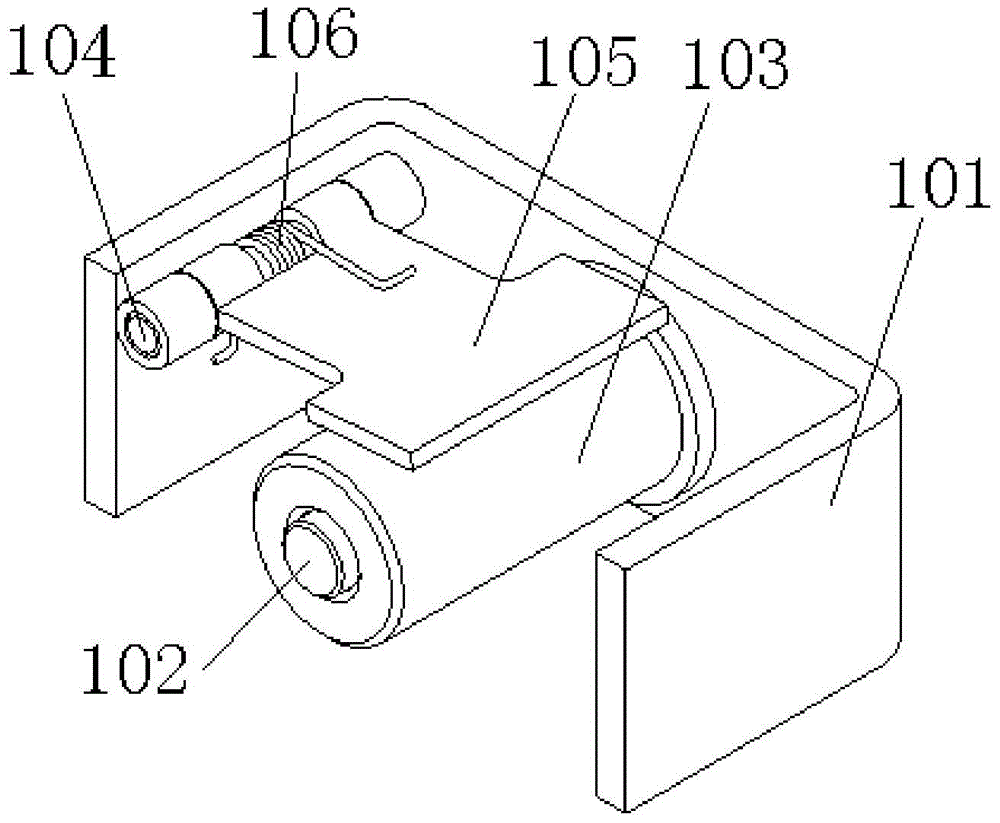
[0034] Such as figure 1 As shown, the pin connection mechanism of the present embodiment comprises a grooved plate 101, a slide pin 102, a round pin 103, a rotating mechanism 104, a baffle plate 105 and a torsion spring 106; The sliding pin 102 is connected, and the round pin 103 is slidingly sleeved on the sliding pin 102; the side plate of the groove plate 101 is connected to the baffle plate 105 by rotating the rotating mechanism 104 parallel to the sliding pin 102, and the torsion spring 106 is fixedly sleeved on the rotating mechanism 104 One end of the torsion spring 106 is inserted on the side plate of the grooved plate 101, and the other end of the torsion spring 106 is pressed on the baffle 105, and then the baffle 105 is pressed on the round pin 103.

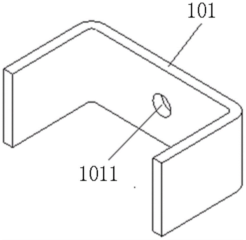
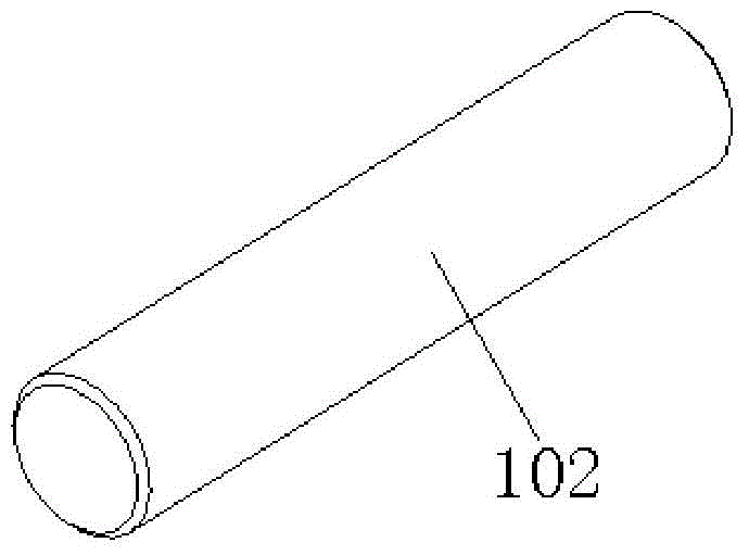
[0035] In the above embodiment, if figure 2 , image 3 As shown, the grooved plate 101 can be a U-shaped plate or an L-shaped plate. In the embodiment of the present invention, the grooved plate 101 adopts a U-shape...

Embodiment 2

[0040] Such as Figure 9 As shown, the pin connection mechanism of the present embodiment includes a base plate 201, a round pin 202, a sliding pin 203, two cylindrical pins 204, a baffle plate 205 and a torsion spring 206; The sliding pin 203 of the pin 202, the bottom plate 201 on both sides of the sliding pin 203 are respectively fixed with cylindrical pins 204 for fixing with the parts to be pinned, and one of the cylindrical pins 204 is sequentially sleeved with a baffle plate 205 and a torsion spring 206. One end of the spring 206 is inserted on the bottom plate 201 , and the other end of the torsion spring 206 is pressed on the baffle 205 , so that the baffle 205 is pressed on the round pin 202 .

[0041] In the above embodiment, if Figure 10 ~ Figure 13As shown, the bottom plate 201 can be a rectangular plate, and three through holes 2011 are arranged at intervals on the axis of the rectangular plate, wherein the middle through hole 2011 is fixedly connected to the s...


PUM


Abstract

The invention relates to a pin connection mechanism which is characterized by comprising a groove-shaped plate, a sliding pin, a round pin, a rotating mechanism, a baffle plate and a torsion spring, wherein a bottom plate of the groove-shaped plate is fixedly connected with the sliding pin; the sliding pin is slidably provided with the round pin in a sleeving way; a side plate of the groove-shaped plate is rotationally connected with the baffle plate through the rotating mechanism which is parallel to the sliding pin; the torsion spring is fixedly arranged on the rotating mechanism in a sleeving manner; and one end of the torsion spring is inserted into the side plate of the groove-shaped plate, and the other end of the torsion spring is arranged on the baffle plate so that the baffle plate is arranged on the round pin in a pressing way. The pin connection mechanism disclosed by the invention is suitable for an occasion in which frequent pin connection and pin connection elimination are required and can be used for effectively preventing the dropping, mistaken entrance and loss of the round pin.

Description

technical field [0001] The invention relates to a connection mechanism, in particular to a pin connection mechanism which is suitable for frequent insertion and extraction and needs to stop the pin and prevent the loss of the pin after insertion and extraction. Background technique [0002] Pin connection is a very convenient connection method, which is widely used in various fields, especially in railway wagons and vehicles. For example, when transporting the braces and braces in the concrete bridge support device, the braces and the braces are connected together by pinning when the vehicle loads the concrete bridge, and the pinning of the braces and the braces is released when the vehicle unloads the concrete bridge The upper strata lifting floor of double-deck transportation car special vehicle also is to coordinate the loading and unloading of automobile to carry out pin connection and unpin connection equally. [0003] At present, the commonly used pin connection metho...

Claims


Application Information

Patent Timeline
Patent Type & Authority Patents(China)
IPC IPC(8): F16C11/04
Inventor 廖小平
Owner CRRC QIQIHAR ROLLING CO LTD
Why Eureka
Try Eureka