
Structure for preventing encoder button from coming out of place

An anti-off structure and encoder technology, which is applied in the field of anti-off structures of encoder knobs, can solve the problems that it is difficult to avoid the elastic locking claws coming out, and it is difficult to avoid the accidental disintegration of the anti-off structures of the encoder knobs, so as to prevent the off-off Effect

Inactive Publication Date: 2012-11-28
SHARP KK
View PDF3 Cites 5 Cited by
  • Summary
  • Abstract
  • Description
  • Claims
  • Application Information

AI Technical Summary

Problems solved by technology

[0006] In the conventional anti-off structure of the encoder knob, since the elastic locking claw portion of the rotating flange is only inserted and locked into the locking hole of the rotor, when the user pulls the knob with a force greater than a specified force, When pulling the rotating flange, it is difficult to prevent the elastic locking claws from protruding from the multiple locking holes, so it is difficult to avoid accidental disassembly of the anti-off structure of the encoder knob

Method used


Image

  • Structure for preventing encoder button from coming out of place
  • Structure for preventing encoder button from coming out of place
  • Structure for preventing encoder button from coming out of place

Examples


Embodiment Construction

[0047] Hereinafter, the present invention will be specifically described based on the illustrated embodiments.

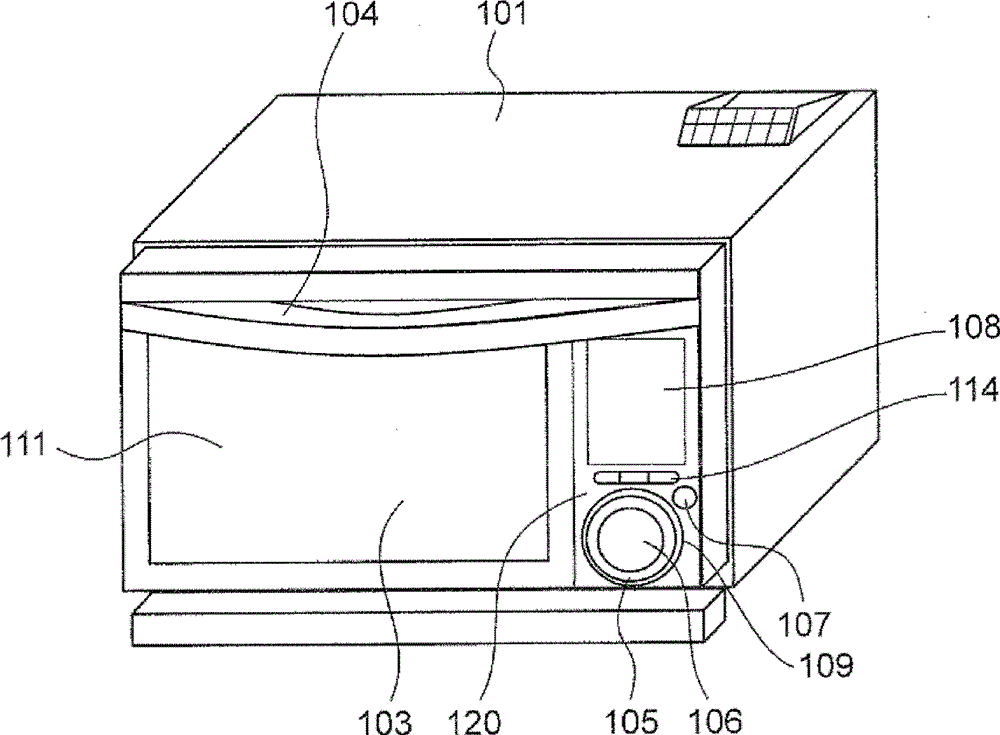
[0048] figure 1 It is a perspective view which looked at the steam cooker which concerns on one Embodiment of this invention from the front side.

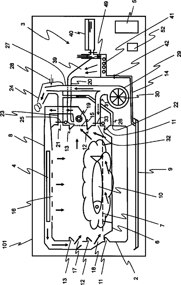
[0049] Described steam cooker comprises: the shell 101 of cuboid shape, heating chamber 2 (referring to figure 2 ), switch door 103 and handle structure 104. The opening and closing door 103 opens and closes the opening of the door frame 120 on the front side of the heating chamber 2 by rotating about its lower edge as a substantially central axis. A heat-resistant glass 111 is disposed at a substantially central portion of the opening and closing door 103 , through which the user can visually confirm the state of the heating chamber 2 . A gasket (not shown) made of heat-resistant resin is fixedly attached to the rear surface of the opening and closing door 103 so as to surround the heat-resistant glass 111 . In add...


PUM


Abstract

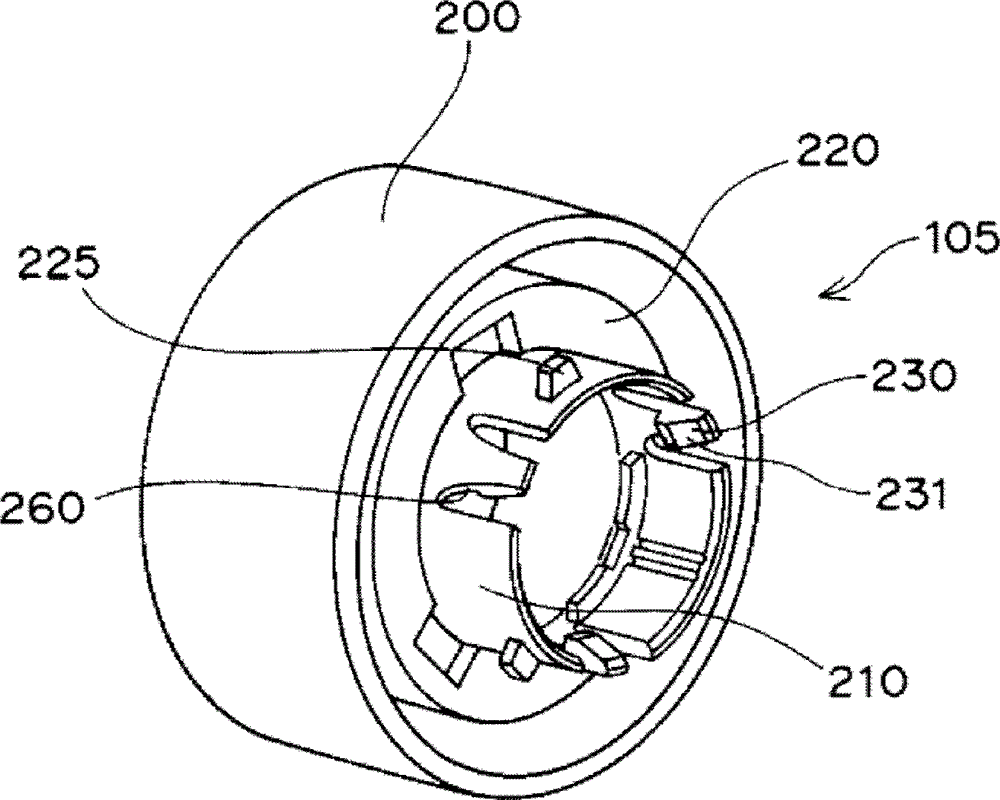
Inner claws for an engaging section (210) for a dial (105) are engaged with engaging grooves in a rotary encoder (320). The dial (105) has formed thereon retaining projections projecting outward radially from the engaging section (210) at intervals in the circumferential direction. A through-hole (500) through which the engaging section (210) can pass and recesses through which the retaining projection can pass are formed in a door frame (120). The retaining projections are adapted so that the projections can pass through the recesses only when the phase in the circumferential direction of the projections coincides with that of the recesses. The retaining projections are positioned on the opposite side of an operation section (200) in the recesses to enable the retaining projections to freely rotate in synchronism with the rotation of the operation section (200).

Description

technical field [0001] The invention relates to an anti-off structure of an encoder knob, in particular to an anti-off structure of an encoder knob suitable for use on heating cookers such as microwave ovens or steam cookers. Background technique [0002] Japanese Patent Laid-Open Publication No. 2005-197070 (Patent Document 1) discloses a conventional encoder knob anti-off structure. [0003] The anti-off structure of the encoder knob has an annular rotating flange and a rotor, and the rotating flange has a plurality of elastic locking claws protruding from its lower surface. The plurality of elastic latching claws are arranged at intervals in the circumferential direction. The front end of each of the elastic latching claws is formed in an L-shape toward the inside. [0004] On the other hand, the rotor has a rotatable cylindrical portion, and a plurality of locking holes are formed on the outer peripheral surface of the cylindrical portion, and the plurality of locking ...

Claims


Application Information

Patent Timeline
Patent Type & Authority Applications(China)
IPC IPC(8): H01H19/14F24C15/00H01H3/08
CPCH01H2019/008F24C7/082H01H2239/038H01H19/14H01H3/10F16B2200/69
Inventor 西岛正浩伊奈典子
Owner SHARP KK
Learn More