Measuring Method of Track Stiffness Based on Machine Vision

A technology of machine vision and measurement method, applied in the direction of measurement devices, instruments, etc., can solve the problem of different loads on two occasions

Active Publication Date: 2017-05-31
WUHAN WUDA ZOYON SCI & TECH
View PDF5 Cites 0 Cited by
  • Summary
  • Abstract
  • Description
  • Claims
  • Application Information

AI Technical Summary

Problems solved by technology

This measurement system needs to perform two measurements on the same track, the two loads are different, the problem is found in the first time, and the problem is located in the second time

Method used


Image

  • Measuring Method of Track Stiffness Based on Machine Vision
  • Measuring Method of Track Stiffness Based on Machine Vision
  • Measuring Method of Track Stiffness Based on Machine Vision

Examples


Embodiment Construction

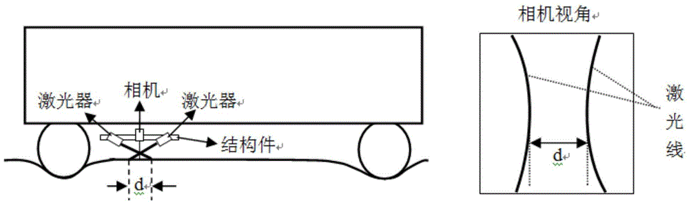
[0027] The measurement system involved in this specific embodiment includes two one-line lasers and a camera, and the camera is used as a machine vision sensor. As shown in the figure, the camera and the measurement carrier are fixed by structural members, so that the camera is installed directly above the rail surface, and the camera moves synchronously with the wheel in the direction perpendicular to the driving direction. Two in-line lasers are installed on the same level as the vision sensor. The two in-line lasers cross and emit in-line lasers respectively, and the camera captures the imaging of the two in-line lasers on the rail above the track, which is figure 2 Laser line shown. Among them, the laser line on the left is the imaging of the line laser on the right side of the camera, and the laser line on the right is the imaging of the line laser on the left side of the camera. The shortest distance between the two laser lines is d.

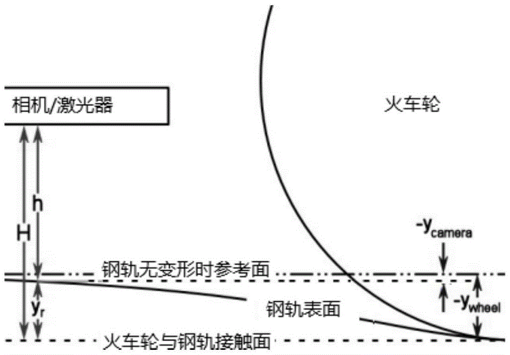
[0028] Such as image 3 As sho...


PUM


Abstract

The invention discloses a rail rigidity measuring method based on machine vision. Through a ranging method of laser and visual sensor, vertical deflection of a steel rail is obtained, so as to obtain rail rigidity. Through measuring the distance from a visual sensor to the cross section of the steel rail, and compensating measuring errors generated by up-down vibration of a vehicle and inclination angle measurement, the vertical deflection of the steel rail is obtained, so as to obtain rail rigidity. The method supports dynamic acquisition. The method uses a cross section ranging way. Compared with a conventional single-point ranging method, the method reduces and even eliminates influences of nonuniform abrasion on the surface of the steel rail, irregular weld zones, irregular rail, and other factors on measuring results to a large extent. On the basis of rapid measurement, the method accurately measures the rail rigidity, and indirectly reduces consumption of cost.

Description

technical field [0001] The invention relates to a method for measuring rail stiffness. Background technique [0002] Rail stiffness refers to the vertical load (unit: kN / mm) required for the rail to produce unit subsidence, where the unit subsidence of the rail refers to the unit vertical deformation of the rail under the vertical pressure load. [0003] Track stiffness is an important parameter that affects the vibration and deformation of the track structure, the safety and stability of train operation, and the workload of track maintenance and repair. Reasonable track stiffness can not only ensure the safe and stable operation of the train, but also effectively slow down the wheel-rail interaction. Reduce the dynamic stress of the track structure and keep the geometric state of the track in good condition, thereby reducing the maintenance and repair workload of the rail. [0004] At present, there are many methods that can be used to measure the vertical stiffness of the...

Claims


Application Information

Patent Timeline
Patent Type & Authority Patents(China)
IPC IPC(8): G01B21/32
CPCG01B21/32
Inventor 李清泉曹民张德津林红谢和礼李辉张志刚文艺
Owner WUHAN WUDA ZOYON SCI & TECH
Why Eureka
Try Eureka