Power generating element

A technology of power generation components and composite rods, which is applied in the direction of electrical components, generators/motors, circuits, etc., can solve problems such as difficult stress, and achieve the effect of improving power generation efficiency

Inactive Publication Date: 2015-04-08
MITSUMI ELECTRIC CO LTD
View PDF5 Cites 7 Cited by
  • Summary
  • Abstract
  • Description
  • Claims
  • Application Information

AI Technical Summary

Problems solved by technology

However, if the distance between the magnetostrictive rods is increased, it tends to become more difficult to generate uniform stress on one magnetostrictive rod.

Method used


Image

  • Power generating element
  • Power generating element
  • Power generating element

Examples


no. 1 approach >

[0050] First, a first embodiment of the power generating element of the present invention will be described.

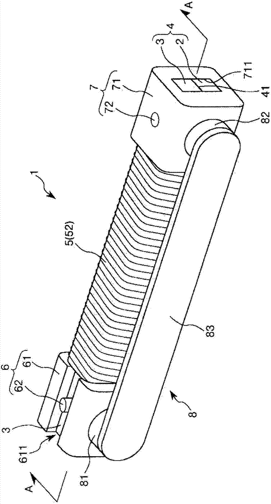
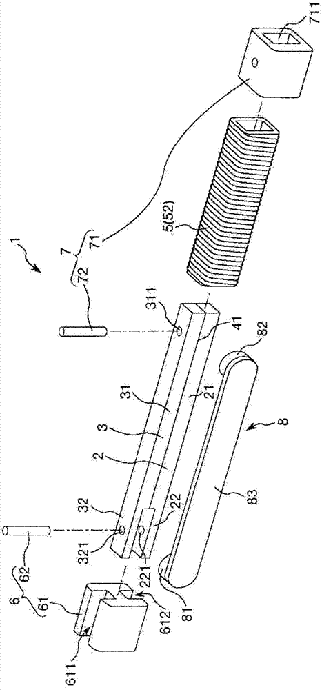
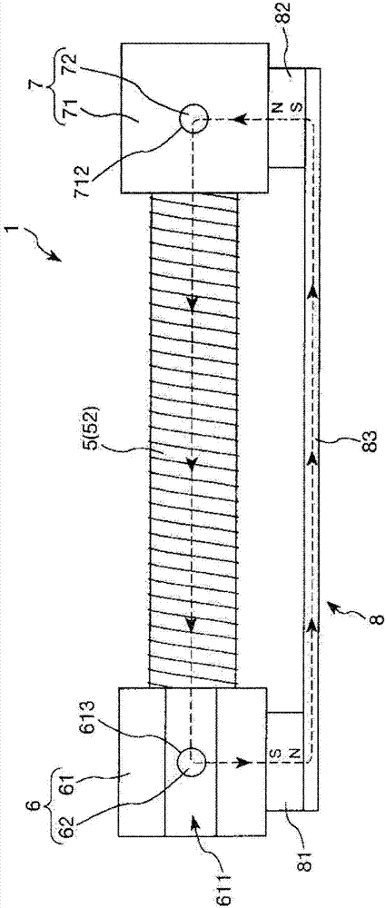
[0051] figure 1 It is a perspective view showing the first embodiment of the power generating element of the present invention, figure 2 yes figure 1 An exploded perspective view of the power generating element shown, image 3 yes figure 1 A top view of the generating element shown, Figure 4 yes figure 1 Longitudinal sectional view of the power generating element shown ( figure 1 A-A line sectional view in), Figure 5 It is an analytical diagram analyzing the stress generated in the composite rod.

[0052] Also, in the following description, the figure 1 , figure 2 as well as Figure 4 the upper side of the image 3 The front side of the paper is called "upper" or "above", and the figure 1 , figure 2 as well as Figure 4 the lower side of the middle and image 3 The inside of the paper is called "down" or "below". Additionally, the Figure ...

no. 2 approach >

[0113] Next, a second embodiment of the power generating element of the present invention will be described.

[0114] Figure 6 It is a longitudinal sectional view showing a second embodiment of the power generating element of the present invention.

[0115] Also, in the following description, the Figure 6 The upper side in is referred to as "upper" or "above", and the Figure 6 The lower side in is called "lower" or "below". Additionally, the Figure 6 The right side is called the "front end" and the left side is called the "base end".

[0116] Hereinafter, the power generating element of the second embodiment will be described focusing on points that are different from the power generating element of the first embodiment described above, and descriptions of the same matters will be omitted.

[0117] The power generating element 1 of the second embodiment is the same as the power generating element 1 of the above-mentioned first embodiment except that the overall shape ...

no. 3 approach >

[0122] Next, a third embodiment of the power generating element of the present invention will be described.

[0123] Figure 7 It is a longitudinal sectional view showing a third embodiment of the power generating element of the present invention.

[0124] Also, in the following description, the Figure 7 The upper side in is called "upper" or "above", and the lower side is called "lower" or "below". Additionally, the Figure 7 The right side is called the "front end" and the left side is called the "base end".

[0125] Hereinafter, the power generating element of the third embodiment will be described focusing on points that are different from the power generating elements of the first and second embodiments described above, and descriptions of the same matters will be omitted.

[0126] In the power generating element 1 of the third embodiment, the relationship between the thickness of the main body portion 21 of the magnetostrictive rod 2 and the thickness of the main bo...


PUM


Abstract

A power generating element having arranged side-by-side therein a magnetostrictive rod comprising a magnetostrictive material and causing a line of magnetic force to pass through in the axial direction and a reinforcing rod comprising a non-magnetic material and having a function that applies an appropriate stress to the magnetostrictive rod; having a composite rod comprising mutually bonded bonding sections and a coil arranged such that the line of magnetic force passes through in the axial direction and generating voltage on the basis of changes in the density thereof; and configured so as to cause the density of the line of magnetic force to change, by relatively displacing one end of the composite rod relative to the other end, in a direction substantially vertical relative to the axial direction thereof, and causing the magnetostrictive rod to expand and contract.

Description

technical field [0001] The present invention relates to power generating elements. Background technique [0002] In recent years, research has been conducted on power generating elements that generate power by utilizing changes in the magnetic permeability of magnetostrictive rods made of magnetostrictive materials (for example, refer to Patent Document 1). [0003] The power generating element includes, for example: a pair of magnetostrictive rods arranged side by side; a coupling yoke connecting the above-mentioned magnetostrictive rods; a coil provided so as to surround each magnetostrictive rod; permanent magnet and back yoke. And, when an external force is applied to the coupling yoke in a direction perpendicular to the axial direction of the magnetostrictive rods, one magnetostrictive rod is deformed to expand, and the other magnetostrictive rod is deformed to contract. . At this time, the density of the lines of force (magnetic flux density) passing through each ma...

Claims


Application Information

Patent Timeline
Patent Type & Authority Applications(China)
IPC IPC(8): H02N2/00H01L41/06
CPCH02N2/18H01L41/125H02N2/186H10N35/101
Inventor 古河宪一沼宫内贵之
Owner MITSUMI ELECTRIC CO LTD
Why Eureka
Try Eureka