Medical infusion device

A technology of an infusion device and a liquid storage box, which is applied in the field of medical devices, can solve the problems of patient discomfort, fast liquid medicine, and inability to drip at a constant speed and stability, and achieve the effects of ensuring liquid level, easy replacement, and reducing complexity.

Inactive Publication Date: 2015-04-22
陶杰
View PDF0 Cites 3 Cited by
  • Summary
  • Abstract
  • Description
  • Claims
  • Application Information

AI Technical Summary

Problems solved by technology

[0005] The technical problem to be solved by the present invention: in the initial period of time in the existing infusion set, the liquid medicine is always dripped very quickly, which cannot be dripped at a uniform speed and is likely to bring discomfort to the patient's body; and when the infusion speed is fast, It is also prone to the phenomenon that the liquid medicine cannot be dripped at a uniform speed

Method used


Image

  • Medical infusion device
  • Medical infusion device

Examples


Embodiment 1

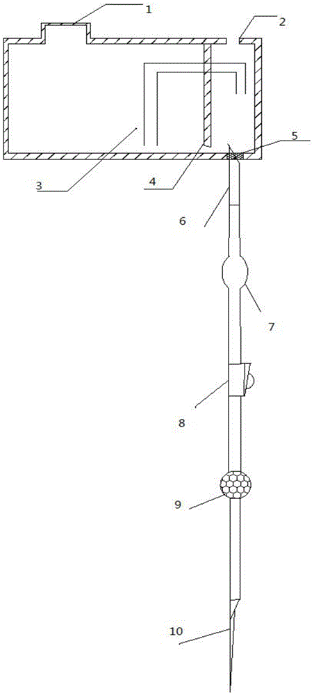
[0019] Embodiment 1: as figure 1 Shown: a medical infusion device, including a liquid storage box, a partition, and an air guide tube; the partition divides the liquid storage box into a left chamber and a right chamber; the volume of the left chamber is greater than that of the right chamber; The bottom of the partition is provided with a communicating hole; one port of the air duct is funnel-shaped, the air duct passes through the partition, one end of the funnel-shaped port is located at the bottom of the left chamber, and the other end is located in the right chamber The top of the left chamber is provided with a liquid filling hole, and the described liquid filling hole is provided with a detachable plug; the top of the right chamber is provided with an air inlet; the bottom of the right chamber An infusion hole is provided, and a rubber stopper is arranged on the infusion hole; a bottle stopper piercer, a drip funnel, a flow rate regulator, a liquid medicine filter, an i...

Embodiment 2

[0020] Embodiment 2: On the basis of embodiment 1, the volume of the left chamber is 800 milliliters, and the volume of the right chamber is 8 ml.

[0021] The working principle of the present invention: after adding the liquid medicine to the left chamber, the liquid medicine in the right chamber will submerge the port of the airway tube. Since the volume of the right chamber is very small, the liquid level will soon be equal to that of the airway tube in the right chamber. The port is flat, once the liquid level is lower than the height of the port of the air guide tube, the air will quickly enter the left chamber through the air guide tube, the pressure at the bottom of the left chamber will increase, and the liquid in the left chamber will enter through the communication hole to the right chamber, and then the right chamber liquid level floods the airway port again and is level with the airway port, so the liquid level in the right chamber is almost constant all the time, s...


PUM


Abstract

The invention discloses a medical infusion device which comprises a liquid storage box, a partition plate and an air guide pipe. The partition plate divides the liquid storage box into a left cavity and a right cavity. The size of the left cavity is larger than that of the right cavity. The bottom of the partition plate is provided with a communication hole. One end opening of the air guide pipe is in a funnel shape, and the air guide pipe penetrates through the partition plate. The end, with the end opening in the funnel shape, of the air guide pipe is located at the bottom of the left cavity, and the other end of the air guide pipe is located in the right cavity. The top of the left cavity is provided with a liquid adding hole, and the liquid adding hole is provided with a detachable stopper. The top of the right cavity is provided with an air inlet hole. The bottom of the right cavity is provided with an infusion hole, and the infusion hole is provided with a rubber stopper. One end of an infusion hose is provided with a bottle stopper puncturing device, and the other end is provided with a vein needle. The infusion hose is provided with a drip chamber, a flow speed adjuster and a liquid medicine filter. The bottler stopper puncturing device penetrates through the infusion hole. According to the medical infusion device, the liquid medicine can drip stably at a constant speed no matter whether the infusion speed is high or low.

Description

technical field [0001] The invention relates to the technical field of medical instruments, in particular to a medical transfusion device. Background technique [0002] The medical infusion bottle is a bottle of liquid that is used for infusion in the human body when the patient is infused. The infusion set is a common disposable medical consumable that is used for intravenous infusion after aseptic treatment to establish a channel between the vein and the liquid medicine. Generally, it is composed of a venous needle, a protective cap, an infusion hose, a liquid medicine filter, a flow rate regulator, a drip funnel, a cork puncturer, an air inlet pipe, and an air filter connection. Under the action of atmospheric pressure, the liquid in the infusion bottle flows into the drip funnel along the thinner infusion hose, and when the water column pressure in the drip funnel is greater than the venous pressure, the liquid in the bottle flows into the vein along the hose. Before u...

Claims


Application Information

Patent Timeline
Patent Type & Authority Applications(China)
IPC IPC(8): A61M5/14A61M5/162A61M5/168
CPCA61M5/14A61M5/162A61M5/16822A61M2005/1401
Inventor 陶杰
Owner 陶杰
Why Eureka
Try Eureka