Self-locking two-platen machine mold clamping mechanism

The technology of a clamping mechanism and a two-platen machine, applied in the field of injection molding machines, can solve the problems of complex hydraulic system and high energy consumption, and achieve the effect of reducing energy consumption

Inactive Publication Date: 2017-03-08
CHINA JILIANG UNIV
View PDF6 Cites 0 Cited by
  • Summary
  • Abstract
  • Description
  • Claims
  • Application Information

AI Technical Summary

Problems solved by technology

[0004] In view of this, the present invention provides a self-locking two-platen mold clamping mechanism to solve the technical problems of complex hydraulic systems and high energy consumption in the prior art, and proposes a self-locking mold clamping structure with low energy consumption to Solve the above technical problems

Method used


Image

  • Self-locking two-platen machine mold clamping mechanism
  • Self-locking two-platen machine mold clamping mechanism
  • Self-locking two-platen machine mold clamping mechanism

Examples


Embodiment Construction

[0019] The present invention will be further described below in conjunction with the accompanying drawings and specific embodiments, but the present invention is not limited to these embodiments.

[0020] The present invention covers any alternatives, modifications, equivalent methods and schemes made on the spirit and scope of the present invention. In order to provide the public with a thorough understanding of the present invention, specific details are set forth in the following preferred embodiments of the present invention, but those skilled in the art can fully understand the present invention without the description of these details. In addition, for the sake of illustration, the drawings of the present invention are not completely drawn according to the actual scale, and are described here.

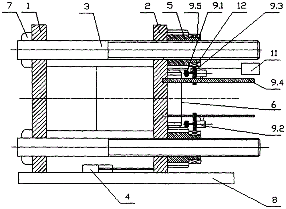
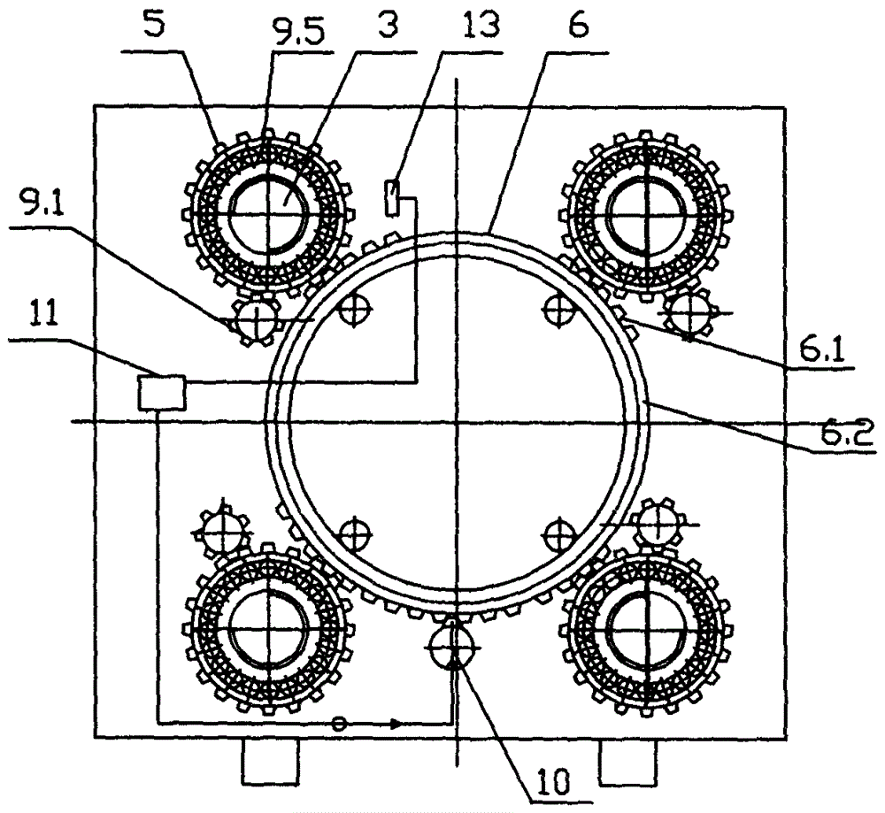
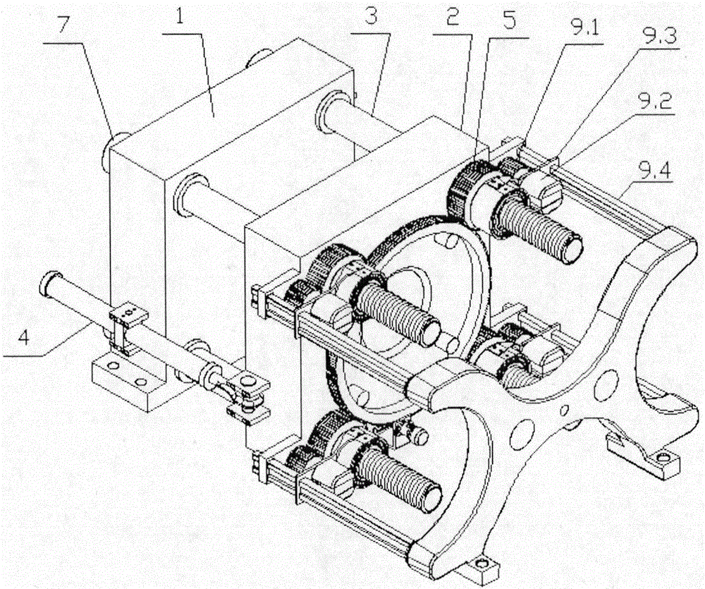
[0021] Such as figure 1 , 2 As shown in and 3, a kind of self-locking type two-platen mold clamping mechanism involved in the present invention includes a fixed template 1, a m...


PUM


Abstract

The invention discloses a mold closing mechanism of a self-locking type two-plate machine. The mold closing mechanism comprises a fixed mold plate (1), a movable mold plate (2), pull rods (3) and a mold moving oil cylinder (4), wherein the fixed mold plate (1) is fixed at one ends of the pull rods (3), the other ends of the pull rods (3) are sleeved by the movable mold plate (2), and a piston end of the mold moving oil cylinder (4) is connected with the movable mold plate (2) to drive the movable mold plate (2) to move; and the mold closing mechanism further comprises a mold locking structure, the mold locking structure comprises rear screw nuts (5) which are in one-to-one correspondence with the pull rods (3), a large gear ring (6) and a power mechanism for driving the large gear ring (6) to rotate, the rear screw nuts (5) are screwed on the pull rods (3), the outer edges of the rear screw nuts (5) are set to be like gears, and the large gear ring is meshed with the rear screw nuts (5) under the drive of the power mechanism and drives the rear screw nuts to rotate on the corresponding pull rods. According to the mechanism disclosed by the invention, a mold locking oil cylinder is not required, and energy consumption in mold locking is reduced by self-locking of the mechanism.

Description

technical field [0001] The invention relates to the field of injection molding machines, in particular to a self-locking two-platen machine mold clamping mechanism. Background technique [0002] The mold clamping structure of the existing two-platen injection molding machine mainly includes hydraulic direct locking type and compound type. Among them, the working process of the hydraulic direct locking type is mainly: firstly, the movable template is moved through the fast mold moving cylinder, and then the tie rod is locked through the brake structure, and then the mold is locked through the locking cylinder. The hydraulic direct locking type has automatic adjustment. mold function, but the required hydraulic system is relatively complex, the reliability is poor, and the occupied space has no obvious advantages compared with the three-platen injection molding machine, especially when the clamping force is large, four very large The oil cylinder has a large power, and it nee...

Claims


Application Information

Patent Timeline
Patent Type & Authority Patents(China)
IPC IPC(8): B29C45/68
CPCB29C45/68B29C2045/685B29C2045/686
Inventor 饶宾期潘宏伟周宏伟欧阳华兵
Owner CHINA JILIANG UNIV
Why Eureka
Try Eureka