
A parallel linkage stiffness test bench

A technology of dynamic stiffness and test bench, which is applied in the field of mechanical vibration and shock, can solve the problems of not considering the impact of vibration, affecting the test results of dynamic stiffness, unfavorable use and maintenance, etc., so as to save design costs, widely apply and promote the prospect , good safety and experimental accuracy

Active Publication Date: 2018-05-29
GUANGXI UNIVERSITY OF TECHNOLOGY
View PDF8 Cites 0 Cited by
  • Summary
  • Abstract
  • Description
  • Claims
  • Application Information

AI Technical Summary

Problems solved by technology

[0003] The existing experimental methods at home and abroad are basically to complete the experiment through the cooperation of the hydraulic testing machine and the actuator. However, the current technology generally uses a single suspension device to perform a one-way stiffness test, and does not consider other factors during the test. The influence of direction on vibration, and because of the complex structure, installation and disassembly are very troublesome, which is not conducive to use and maintenance
Moreover, this kind of equipment can only test the stiffness of one rubber part at a time. During the repeated clamping process, it may cause excessive bending and torsion of the rubber, and deformation will affect the dynamic stiffness test results.
Because the rubber mount is basically only subjected to vertical vibration excitation when used as a shock absorber, if the experimental data is distorted due to clamping problems during the experimental test, the collected data will have a large error , resulting in inaccurate test results, which will affect the actual performance of the product, prone to omissions, and make unqualified products leave the factory

Method used


Image

  • A parallel linkage stiffness test bench
  • A parallel linkage stiffness test bench
  • A parallel linkage stiffness test bench

Examples


Embodiment 1

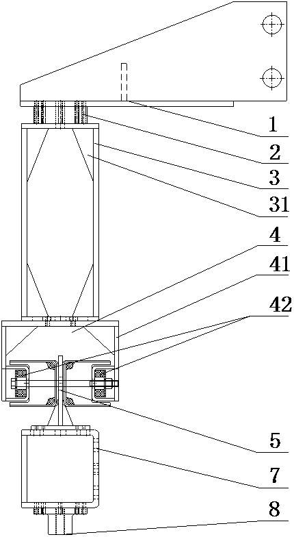
[0019] Example 1 as figure 1 As shown, the parallel linkage stiffness test bench includes force sensor 2, support block 3, parallel fixture 4, connector 5, vibrator 7 and acceleration sensor 8 installed in a straight line, force sensor 2 and support block 3 One end of the support block 3 is connected to detect the change of the force of the entire test bench in real time, and the other end of the support block 3 is connected to the parallel clamp 4 .

[0020] The parallel linkage stiffness test bench also includes a mounting base 1 for connecting the entire testing bench to the pressure testing machine, and the mounting base 1 can move up and down along the track of the pressure testing machine.

[0021] The support block 3 is a rectangular frame structure, and reinforcement plates 31 are welded around the inside of the frame body, and the other end of the support block 3 is connected with the parallel fixture 4 .

[0022] The parallel fixture 4 includes two parts: a mounting...

Embodiment 2

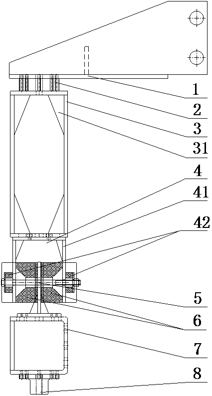
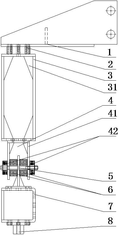
[0027] Example 2 as Figure 2-Figure 3 As shown, the difference from Example 1 is that the clamping method of front suspension or rear suspension is adopted, and the installation position of the rubber parts is adjusted through the left and right clamping parts 42 of the parallel clamp 4, and the other rubber parts are tested. The dynamic stiffness of the X-direction and Y-direction in the two directions of the parts expands the scope of application of the test bench.

[0028] The working principle and test method are the same as in Example 1.


PUM


Abstract

The invention provides a parallel linkage stiffness test bench, which includes a mounting seat, a force sensor, a support block, a parallel clamp, a connector, a vibrator, and an acceleration sensor device. To connect the entire test bench to the pressure testing machine, a force sensor is installed on the mounting base, the force sensor is connected to one end of the support block, and the other end of the support block is connected to the parallel fixture, which is a U-shaped structure, including two clamps The holding part is welded with reinforcing ribs inside. The overall steel structure can hold two rubber test pieces at the same time. The installation direction can be changed. There is a connecting piece in the middle of the two holding parts. Vibrator and acceleration sensor device. The invention has reasonable structural design, low manufacturing cost and good detection effect.

Description

technical field [0001] The invention relates to the field of mechanical vibration and impact, in particular to a parallel linkage stiffness test bench. Background technique [0002] With the continuous development of NVH technology in China, rubber shock absorbers, as the most cost-effective shock-absorbing equipment, are widely used by many companies. The dynamic characteristic parameter of the shock absorber is an important index to measure the performance of the automobile mount. At present, the dynamic characteristics of the rubber mount are tested mainly by simulating the excitation conditions of the rubber mount on the test bench, and studying the vibration of the rubber mount at different excitation frequencies. And the dynamic characteristic parameters under the excitation amplitude, so as to obtain the dynamic stiffness value under different frequencies and different amplitudes. [0003] The existing experimental methods at home and abroad are basically to complete...

Claims


Application Information

Patent Timeline
Patent Type & Authority Patents(China)
IPC IPC(8): G01M7/06G01M7/08
Inventor 李冰徐武彬周德俭陈其兵汤毓曹照均
Owner GUANGXI UNIVERSITY OF TECHNOLOGY
Learn More