Lighting lamp

A technology of lighting fixtures and turntables, which is applied in the field of lighting and can solve problems such as limited angle adjustment

Active Publication Date: 2015-04-29
SUZHOU OPPLE LIGHTING
View PDF6 Cites 0 Cited by
  • Summary
  • Abstract
  • Description
  • Claims
  • Application Information

AI Technical Summary

Problems solved by technology

However, the rotating shaft of this lighting fixture is generally arranged along the radial direction of the lighting fixture, the main lamp body can only swing around the rotating shaft, and the angle adjustment is limited, which sometimes cannot meet the needs

Method used


Image

  • Lighting lamp
  • Lighting lamp
  • Lighting lamp

Examples


Embodiment Construction

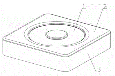
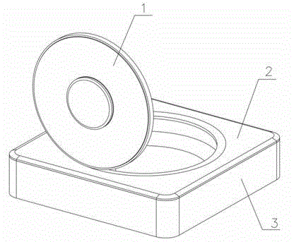
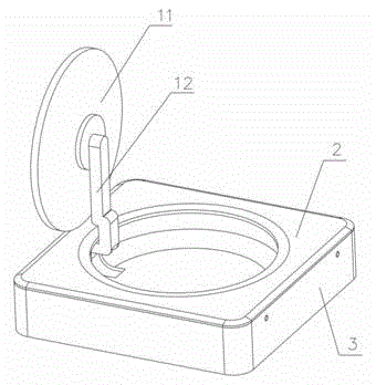
[0027] Combine below Figure 1 to Figure 10 An embodiment of the present invention will be described in detail. The lighting fixture of this embodiment includes a casing, a turntable 5 and a light source assembly, on which a light source 8 is arranged, and the light source 8 is an LED light source. The turntable 5 is installed on the housing, and the turntable 5 can rotate around the first axis. What needs to be specially defined is as follows: Figure 9 The vertical centerline of the turntable 5 is the first rotating shaft. The light source assembly is swingably connected to the turntable 5 so that the angle between the light of the light source 8 and the first axis can be adjusted. In this example, if figure 1 with figure 2 As shown, the light source assembly can swing between a position inside the through hole 21 and a position away from the through hole 21, figure 1 As shown, the position of the light source assembly is in the through hole 21, figure 2 What is show...


PUM


Abstract

The invention relates to a lighting lamp. The lighting lamp comprises a shell, a rotating disc and a light source component, wherein a light source is arranged on the light source component; the rotating disc is mounted on the shell, and can rotate around a first axis; the light source component is connected with the rotating disc in a swing manner so as to adjust the angle between the light ray of the light source and the first axis. The lighting lamp can freely adjust the lighting area and the lighting angle of the lighting lamp, so that the lighting demands under various circumstances can be satisfied.

Description

technical field [0001] The invention relates to the lighting field, in particular to a lighting fixture. Background technique [0002] At present, a lighting fixture on the market includes a main lamp body and an installation part, and the installation part is fixed to the ceiling so that the lighting fixture can be fixedly installed. The main lamp body is rotatably connected to the installation part through the rotating shaft, so that the main lamp body can swing around the rotating shaft within a certain angle range to adjust the irradiation angle. However, the rotating shaft of this lighting fixture is generally arranged along the radial direction of the lighting fixture, the main lamp body can only swing around the rotating shaft, and the angle adjustment is limited, which sometimes cannot meet the needs. Contents of the invention [0003] The technical problem to be solved by the present invention is to provide a lighting fixture. [0004] In order to solve the abo...

Claims


Application Information

Patent Timeline
Patent Type & Authority Applications(China)
IPC IPC(8): F21S2/00F21V19/02F21Y101/02
CPCF21K9/00F21V19/02
Inventor 谢建民
Owner SUZHOU OPPLE LIGHTING
Why Eureka
Try Eureka