Light guide plate and backlight module

A backlight module, light guide plate technology, applied in optics, light guides, electric light sources, etc., can solve the problems of edge light leakage, uneven light output, low brightness, etc.

Active Publication Date: 2015-04-29
WISTRON CORP +1
View PDF5 Cites 2 Cited by
  • Summary
  • Abstract
  • Description
  • Claims
  • Application Information

AI Technical Summary

Problems solved by technology

Traditional optical microstructures include hemispherical structures, V-shaped structures and R-shaped structures, but these traditional optical microstructures have disadvantages such as uneven light output, low brightness, and edge light leakage.

Method used


Image

  • Light guide plate and backlight module
  • Light guide plate and backlight module
  • Light guide plate and backlight module

Examples


Embodiment Construction

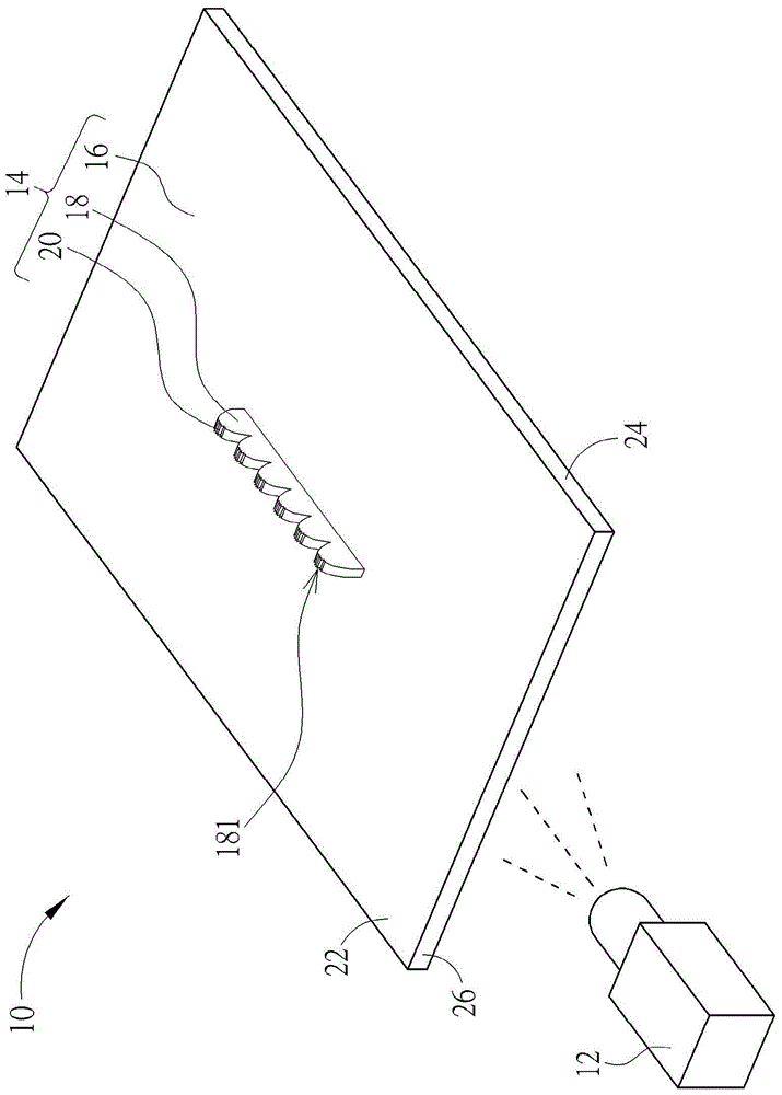
[0046] see figure 1 , figure 1 It is a schematic diagram of a backlight module 10 according to an embodiment of the present invention. The backlight module 10 includes a light source 12 and a light guide plate 14 . The light output from the light source 12 enters the light guide plate 14 from the side, diffuses to the entire light guide plate 14 through the phenomenon of total reflection, and then passes out of the light guide plate 14 from the light output surface to form a surface light source. The light guide plate 14 includes a plate body 16 , at least one prism component 18 and at least one optical microstructure 20 . The plate body 16 has an upper surface 22 , a lower surface 24 and a light-incident side surface 26 . The light source 12 is disposed on the light incident side surface 26 . The prism assembly 18 can be optionally disposed on the upper surface 22 , the lower surface 24 and / or the light-incident side surface 26 . The prism assembly 18 is used to destroy ...


PUM


Abstract

A light guide plate disclosed in the present disclosure includes a board body, a prism component and at least one optical microstructure. The prism component is disposed on at least one surface of the board body. The at least one optical microstructure is disposed on a top end of the prism component. The optical microstructure includes a first light guiding unit and at least two second light guiding units. A first angle is formed between two inclined surfaces of the first light guiding unit, and the first angle is substantially between 45˜60 degrees. The second light guiding units are symmetrically disposed on opposite sides of the first light guiding unit. A second angle is formed between an inclined surface and a bottom surface of each second light guiding unit, and the second angle is substantially between 10˜60 degrees.

Description

technical field [0001] The invention provides a light guide plate and a backlight module, especially a light guide plate with an optical microstructure and a backlight module, so as to improve the brightness and uniformity of light output. Background technique [0002] At present, the main function of the commonly used light guide plate is to guide the point light source into a surface light source. The light emitting unit is arranged on the light incident side of the light guide plate. After the light enters the light guide plate, it will pass through the light guide plate from the light exit surface to form a surface light source. In order to make the light output of the surface light source more uniform and soft, an optical microstructure is usually arranged on the lower surface of the light guide plate, or inside the light guide plate, or on the upper surface of the light guide plate, or on the light incident side of the light guide plate to destroy the light guide plate...

Claims


Application Information

Patent Timeline
Patent Type & Authority Applications(China)
IPC IPC(8): G02B6/00G02B5/04F21S8/00F21V8/00
CPCG02B6/0036G02B6/0053G02B6/0065G02B6/0016
Inventor 牛雅萍刘金涌
Owner WISTRON CORP
Why Eureka
Try Eureka