Backlight module and display device

A technology of backlight module and light guide plate, which is applied in the direction of identification device, installation, optics, etc., can solve the problems such as bright lines at the tail of the optical film, and achieve the effect of improving the bright lines at the tail, reducing shrinkage, and reducing shrinkage deformation

Active Publication Date: 2021-04-27
BOE TECH GRP CO LTD +1
View PDF7 Cites 0 Cited by
  • Summary
  • Abstract
  • Description
  • Claims
  • Application Information

AI Technical Summary

Problems solved by technology

[0005] The purpose of the technical solution of the present invention is to provide a backlight module and a display device to solve the problem of bright lines at the tail due to shrinkage and deformation of the optical film in the display device of the prior art

Method used


Image

  • Backlight module and display device
  • Backlight module and display device
  • Backlight module and display device

Examples


Embodiment Construction

[0026] In order to make the technical problems, technical solutions and advantages to be solved by the present invention clearer, the following will describe in detail with reference to the drawings and specific embodiments.

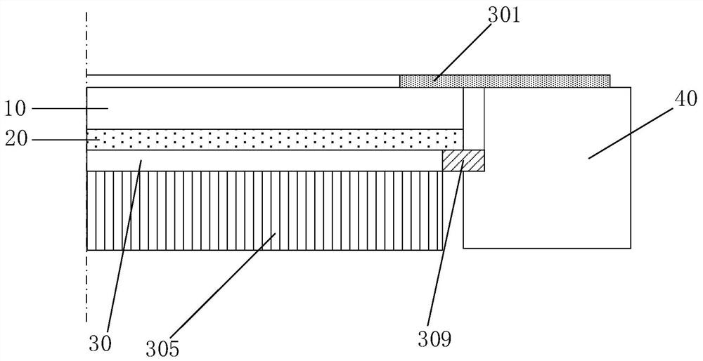
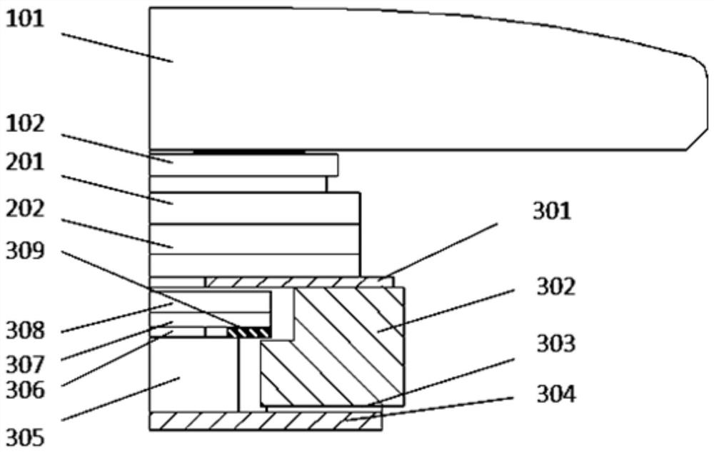
[0027] In the backlight module according to the embodiment of the present invention, the other edge of the light bar is arranged on the optical film, and the first optical film and the second optical film among the at least three optical films are respectively fixedly connected to a fixing component, In order to ensure the fixation of the optical film on the other edge of the light bar, the shrinkage direction of the optical film is from one side of the light bar to the opposite side, so as to reduce the bright line of the optical film on the opposite side of the light bar due to shrinkage deformation probability.

[0028] figure 1 It is a partial cross-sectional structural schematic diagram of the backlight module according to the first embodiment of t...


PUM


Abstract

The present invention provides a backlight module and a display device. The backlight module includes a light bar, a fixing component, and at least three optical films stacked in sequence, wherein the light bar is arranged along the first edge of the optical film. , wherein: at the second edge of the optical film, the first optical film and the second optical film among the at least three optical films are respectively fixedly connected to one of the fixing components; wherein, at least three optical films Among the films, the distance between the first optical film and the third optical film is the farthest, the second optical film is bonded to the third optical film, and the second edge is connected to the third optical film. The first edge is different. In the backlight module described in the embodiment of the present invention, the contraction direction of the second optical film is from one side of the light bar to the opposite side, thereby reducing the overall shrinkage of the opposite edge of the light bar setting edge and improving the tail The effect of bright lines.

Description

technical field [0001] The invention relates to the field of display technology, in particular to a backlight module and a display device. Background technique [0002] With the structural development of electronic equipment, narrow bezels and full screens have become the development trend of display screens on current electronic equipment. In order to increase the screen-to-body ratio of the display screen, the frame of the display screen is getting narrower and narrower. However, based on this development trend, the problem of bright lines at the rear frequently occurs. [0003] At present, the problem of bright lines at the tail of the display screen is greatly affected by factors such as the size of the film material, assembly accuracy, and shrinkage of the film material after the environmental reliability test, but a large proportion of the problem of bright lines at the tail is due to the distance between the lower prism and the plastic frame. Larger cause. [0004] ...

Claims


Application Information

Patent Timeline
Patent Type & Authority Patents(China)
IPC IPC(8): G02B7/18G09F9/00
CPCG02B7/1805G09F9/00
Inventor 唐建业项得胜刘帅南常橙王甲强张彦超于超
Owner BOE TECH GRP CO LTD
Why Eureka
Try Eureka