
Hydrogel 3D printing internal environment control device and method

A 3D printing and control device technology, applied in manufacturing auxiliary devices, processing environment adjustment, additive processing, etc., can solve problems affecting the quality of printed products, deformation of printed structures, dehydration of hydrogel structures, etc., and achieve internal environmental control Stable and efficient, reducing deformation and shrinkage, and reducing water loss

Inactive Publication Date: 2017-07-14
SOUTH CHINA UNIV OF TECH
View PDF4 Cites 8 Cited by
  • Summary
  • Abstract
  • Description
  • Claims
  • Application Information

AI Technical Summary

Problems solved by technology

Since hydrogel is a material with high water content, during the preparation process of hydrogel surface exposure 3D printing, the printed part will leave the solution coating or the protection of the closed liquid container, and will be exposed to the external environment, temperature The temperature and humidity will change, resulting in severe dehydration of the printed hydrogel structure, which will further lead to deformation of the printed structure and affect the quality of the printed product. At the same time, the hydrogel photosensitive solution also needs a relatively constant environment to ensure the stability of its performance.

Method used


Image

  • Hydrogel 3D printing internal environment control device and method
  • Hydrogel 3D printing internal environment control device and method
  • Hydrogel 3D printing internal environment control device and method

Examples


Embodiment

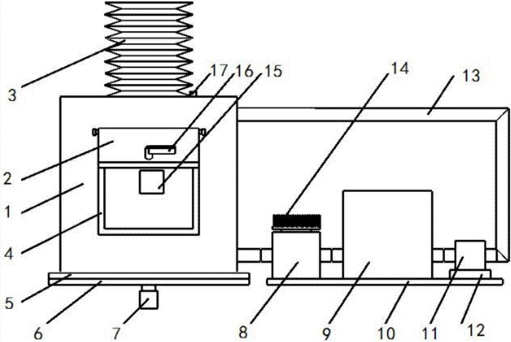
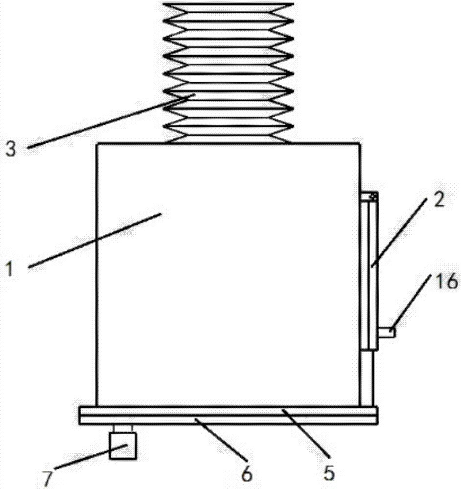
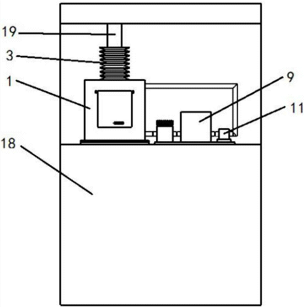
[0026] Such as Figures 1 to 3 shown. The invention discloses a hydrogel 3D printing internal environment control device, which includes a heat insulating glass shell 1, the heat insulating glass shell 1 is bonded to a connecting substrate 5 at the bottom, and the connecting substrate 5 is then co-installed with a printer liquid tank substrate 6. The top of the heat-insulating glass shell 1 is sealed and socketed with the cantilever guide rod 19 of the lifting system of the hydrogel 3D printer 18 through the sealing rubber cover 3; the temperature and humidity sensor 15 is installed on the inner rear wall of the heat-insulating glass shell 1;

[0027] There are upper and lower ventilation holes on the right side wall of the heat-insulating glass shell 1, and the upper ventilation hole is connected to the air pump 11, the ultrasonic humidification generator 9 and the thermoelectric semiconductor square copper tube 8 in turn through the copper tube 13 coated with heat-insulating...


PUM


Abstract

The invention discloses a hydrogel 3D printing internal environment control device and method. The device comprises a thermal insulation glass shell which is bonded to a connecting base plate at the bottom of the thermal insulation glass shell, then the connecting base plate is mounted by being matched with a liquid trough base plate of a printer, the top of the thermal insulation glass shell is connected to a lifting system cantilever guide rod of the hydrogel 3D printer in a sealing and sleeving mode through a seal rubber cover, and a temperature and humidity sensor is mounted on the rear wall of the inside of the thermal insulation glass shell; an upper ventilation hole and a lower ventilation hole are formed in the right side wall of the thermal insulation glass shell; the upper ventilation hole is sequentially connected with an air sucking pump, an ultrasonic wave humidification generator and a thermoelectric semiconductor square copper tube through a copper tube wrapped with thermal insulation cotton and then is connected with the lower ventilation hole of the thermal insulation glass shell, and an enclosed circulation system is formed. According to the control device, simple mounting parts for being connected with the lifting system cantilever guide rod of the printer and the printing liquid trough base plate are designed, the control device is easily applied to hydrogel 3D printing equipment, the control device is simple in whole structure, small in occupied space, easy to perform control and also easy to realize and popularize, and stable and efficient control over the internal environment is achieved.

Description

technical field [0001] The invention relates to the field of 3D printing equipment, in particular to a device and method for controlling the internal environment of hydrogel 3D printing. Background technique [0002] With the application of additive manufacturing in various fields, hydrogel 3D printing is becoming more and more popular in the fields of medicine and light industrial food. How to use hydrogel materials to print more products and print out hydrogel structures with higher precision to become water The key to gel 3D printing technology has attracted the attention of many researchers. Since hydrogel is a material with high water content, during the preparation process of hydrogel surface exposure 3D printing, the printed part will leave the solution coating or the protection of the closed liquid container, and will be exposed to the external environment, temperature The temperature and humidity will change, resulting in severe dehydration of the printed hydrogel ...

Claims


Application Information

Patent Timeline
IPC IPC(8): B29C64/364B33Y40/00
CPCB33Y40/00
Inventor 刘旺玉江小勇李鸣珂孙冬彭羽健谢卫规
Owner SOUTH CHINA UNIV OF TECH
Learn More