Eureka AIR delivers breakthrough ideas for toughest innovation challenges, trusted by R&D personnel around the world.

Driven gear heat treatment method

A heat treatment method and driven gear technology, which is applied in the field of heat treatment of 18Cr2Ni4WA parts, can solve the problems of unmachinable parts of the cavity, influence of the surface of the cavity area, carburization of the cavity area, etc., and achieve high production efficiency, low cost, and improved viscosity. knot effect

Active Publication Date: 2017-04-05
CHINA HANGFA CHANGZHOU LANXIANG MACHINERY CO LTD
View PDF4 Cites 8 Cited by
  • Summary
  • Abstract
  • Description
  • Claims
  • Application Information

AI Technical Summary

Problems solved by technology

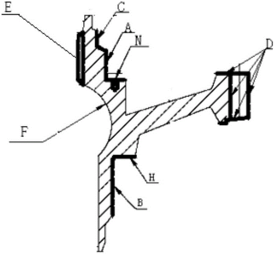
[0003] As a part with special requirements on surface hardness, gears often only require partial carburizing, such as figure 1 As shown, the driven gear used in the aero-engine is made of 18Cr2Ni4WA, that is, the areas A, B, C, D, H, N in the figure and the area of ​​the inner spline E are required to be carburized, and F is the cavity area. No carburization is allowed in this area. In the production process, whether it is gas carburization, liquid carburization or solid carburization, it can only be processed on the surface of the part as a whole, and it is difficult to deal with such special requirements.
After the carburizing of the driven gear is completed, the inner spline E area needs to be machined. During the machining process, the surface of the adjacent cavity area is easily affected, and the surface coating is damaged. In the subsequent quenching, kerosene is often added as a Protect the atmosphere to prevent decarburization of the carburized layer. At this time, it is very easy to cause the cavity area to be carburized. After quenching, the hardness reaches the hardness of the carburized layer, and the subsequent cavity cannot be processed.

Method used


Image

  • Driven gear heat treatment method

Examples


Embodiment 1

[0021] The heat treatment method for the driven gear of this embodiment is to mechanically process the driven gear after quenching and tempering treatment to remove the surface oxide scale; to carry out copper plating treatment on the surface of the driven gear workpiece to ensure that the surface of the part is completely covered with a copper plating protective film; The driving gear is machined to remove the copper-plated protective film attached to the surface of the A, B, C, D, H, N areas and the inner spline E area, which is convenient for subsequent carburizing. Place the driven gear workpiece in a sealed well-type carburizing furnace, drop kerosene as a carburizing agent, keep the temperature at 900°C±10°C, keep it warm for 5 hours, and cool it in air after it comes out of the furnace, and carry out carburizing treatment on the driven gear to obtain The depth of the carburized layer on the surface of the workpiece to be carburized is 0.8-0.9mm; the driven gear workpiece...

Embodiment 2

[0023] The heat treatment method for the driven gear of this embodiment is to mechanically process the driven gear after quenching and tempering treatment to remove the surface oxide scale; to carry out copper plating treatment on the surface of the driven gear workpiece to ensure that the surface of the part is completely covered with a copper plating protective film; The driving gear is machined to remove the copper-plated protective film attached to the surface of the A, B, C, D, H, N areas and the inner spline E area, which is convenient for subsequent carburizing. Place the driven gear workpiece in a sealed well-type carburizing furnace, pass through acetone (other embodiments can also be alcohol, ethanol, ether, etc.) The driven gear is carburized, and the depth of the carburized layer on the surface of the carburized area of ​​the obtained workpiece is 0.9-1.0mm; the driven gear workpiece is tempered at a high temperature at 650°C±10°C, kept for 6 hours, and cooled in th...


PUM


Abstract

The invention relates to a driven gear heat treatment method. According to the scheme of the driven gear heat treatment method, a copper plating layer on the surface of the area where carburization is needed is removed through machining after copper plating treatment is carried out on the whole surface of a driven gear workpiece, then, carburization treatment is carried out, and the purpose that carburization is carried out only in the local area can be achieved; before quenching treatment is carried out, the cavity area, likely to be damaged, of the copper plating layer is coated with an anti-carburization coating, dual-layer protection is carried out on the cavity area, coal oil is added during quenching for atmosphere protection, decarburization on a carburization face can be effectively prevented, carburization can be effectively avoided due to the protection of the anti-carburization coating on the cavity area, and follow-up machining is convenient; and a pressure quenching machine tool is used for oil cooling after quenching, and shrinkage distortion is effectively reduced. By means of the method, the technical effects that carburization is carried out on the designated area of the driven gear, a carburization layer is free of decarburization after carburization is completed and carburization is avoided for the cavity area can be effectively achieved, volume production is easy, and the cost is low.

Description

technical field [0001] The invention relates to the technical field of heat treatment of 18Cr2Ni4WA parts, in particular to a heat treatment method for a driven gear made of 18Cr2Ni4WA. Background technique [0002] 18Cr2Ni4WA has good processability and fatigue resistance, and has relatively ideal hardenability, toughness and good carburization controllability. It is an irreplaceable material for the production of heavy-duty transmission parts. Shafts, crankshafts, spline shafts and other special wear-resistant parts are widely used in the manufacture. Carburizing and nitriding the surface during manufacture is a conventional method to improve the surface hardness of parts. [0003] As a part with special requirements on surface hardness, gears often only require partial carburizing, such as figure 1 As shown, the driven gear used in the aero-engine is made of 18Cr2Ni4WA, that is, the areas A, B, C, D, H, N in the figure and the area of ​​the inner spline E are required to...

Claims


Application Information

Patent Timeline
Patent Type & Authority Applications(China)
IPC IPC(8): C23C8/04C23C8/22C21D1/18C21D9/32
CPCC21D1/18C21D9/32C23C8/04C23C8/22
Inventor 利淑琴吉宜勇
Owner CHINA HANGFA CHANGZHOU LANXIANG MACHINERY CO LTD
Why Eureka
Eureka Blog
Learn More