
A stable structure and a drilling platform construction method based on the stable structure

A technology of drilling platform and construction method, which is applied in the direction of basic structure engineering, underwater structures, artificial islands, etc., and can solve problems such as the inability of steel casings to be self-stabilized, bridge construction disasters, and large wave forces, so as to avoid construction Safety risk, simple construction process, effect of increasing plane rigidity

Active Publication Date: 2016-12-07
CHINA RAILWAY MAJOR BRIDGE ENG GRP CO LTD
View PDF5 Cites 0 Cited by
  • Summary
  • Abstract
  • Description
  • Claims
  • Application Information

AI Technical Summary

Problems solved by technology

With the rapid development of marine engineering, the focus of domestic bridge construction is gradually shifting to the construction of cross-sea bridges. However, the construction of cross-sea bridges has problems such as large wave force, large seabed surface fluctuations, and complicated geological conditions. The insertion depth of the casing cannot meet the requirements of resisting the wave force. When encountering strong wind monsoon climate or typhoon weather, the steel casing will not be able to stabilize itself, which will bring great safety risks to bridge construction
In view of the above problems, the traditional solution is to weld the connection between the steel casings, but in the harsh marine environment and after the construction of the steel casings has been completed, the welding construction difficulty and operational risk of the connection between the steel casings It is very huge; and the construction period is long. If a stable casing group system cannot be formed between the steel casings when a strong monsoon or typhoon comes, it will bring huge disasters and losses to the bridge construction.

Method used


Image

  • A stable structure and a drilling platform construction method based on the stable structure
  • A stable structure and a drilling platform construction method based on the stable structure
  • A stable structure and a drilling platform construction method based on the stable structure

Examples


Embodiment Construction

[0037] The present invention will be described in further detail below in conjunction with the accompanying drawings and embodiments.

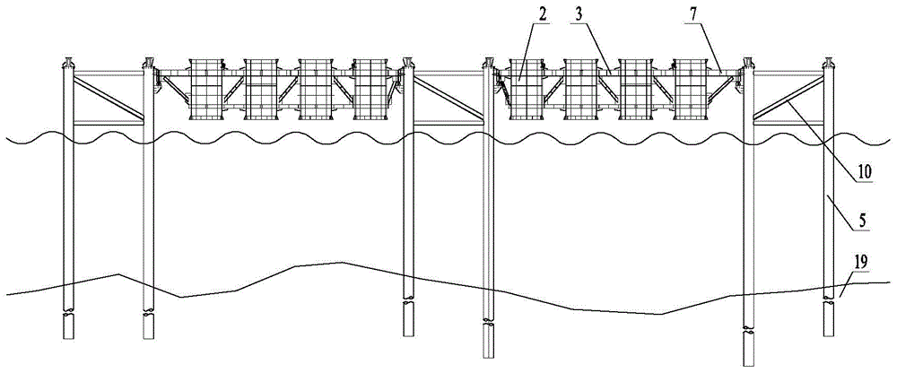
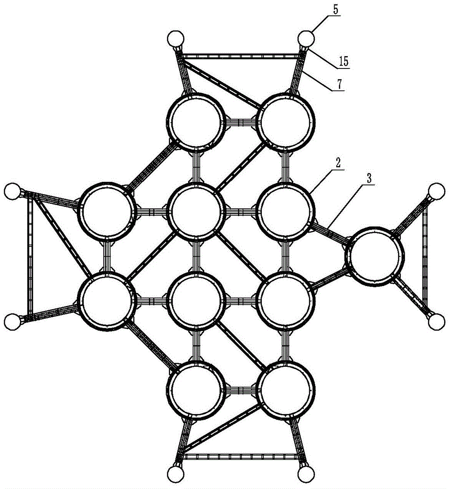
[0038] like Figure 1 to Figure 5 As shown, a stable structure includes several steel pipe piles 5 vertically inserted in the riverbed 19, several platform frames and several groups of position adjustment devices 6. There are a plurality of rectangular frames, and each rectangular frame is provided with a platform frame, and each platform frame is connected to the steel pipe piles 5 corresponding to the side of the rectangular frame through several groups of intermediate couplings 7 . Each platform frame includes several steel casings 2, and each steel casing 2 is provided with a casing stiffening structure for strengthening the steel casing 2 to prevent excessive local stress and deformation of the steel casing 2, and the steel casing 2 The inner diameter of the steel casing 2 is 10-20cm larger than the outer diameter of the steel casing 1, ...


PUM


Abstract

The invention discloses a stable structure and a drilling platform construction method based on the stable structure and relates to the technical field of marine bridge drilling pile foundation construction. Steel pipe piles encircle to form a plurality of rectangular frames on a river bed plane through a pipe pile connecting system, each platform frame is connected with the steel pipe piles positioned on the rectangular edges of the rectangular frames through a plurality of groups of middle connecting systems, every two steel sleeves are connected through a sleeve connecting system, and a steel casing is inserted into each steel sleeve. The drilling platform construction method comprises the following steps: firstly, splicing the platform frames, and arranging the steel pipe piles; secondly, hoisting the platform frames to be erected between the steel pipe piles, adjusting the positions, then fixing the platform frames, and inserting and fixing each steel casing into the corresponding steel sleeve of the corresponding platform frame; finally, paving a platform panel at the top end of each steel casing to complete the construction of a drilling platform. The stable structure acts on the steel casings to form a stable casing group system, the drilling platform is easy and stable to construct, and the construction period of the drilling platform is short.

Description

technical field [0001] The invention relates to the technical field of bored pile foundation construction for offshore bridges, in particular to a stable structure and a drilling platform construction method based on the stable structure. Background technique [0002] In the construction of bored pile foundation of offshore bridges, the main function of the drilling platform is to provide a platform for placing construction materials, tools and machinery. In the construction of traditional drilling platform, the steel casing is inserted first, and then the panel is laid on the top surface of the steel casing to form the drilling platform. When inserting the steel casing, the guide frame is usually used as the auxiliary structure, and the guide frame is welded by steel structure. truss members. With the rapid development of marine engineering, the focus of domestic bridge construction is gradually shifting to the construction of cross-sea bridges. However, the construction o...

Claims


Application Information

Patent Timeline
Patent Type & Authority Patents(China)
IPC IPC(8): E02D13/04E02B17/00
Inventor 毛伟琦刘自明涂满明张立超赵鹍鹏潘东发张红心马涛王东辉张爱花马晓东姚森王寅峰徐启利沈大才王超英潘博胡环顿琳
Owner CHINA RAILWAY MAJOR BRIDGE ENG GRP CO LTD
Learn More