Drip element sealing device, in particular for rolling bearings

一种滚动轴承、密封装置的技术,应用在发动机的密封、轴承组装、球轴承等方向,能够解决尺寸大、高摩擦、低摩擦等问题

Active Publication Date: 2015-05-06
AB SKF
View PDF7 Cites 9 Cited by
  • Summary
  • Abstract
  • Description
  • Claims
  • Application Information

AI Technical Summary

Problems solved by technology

[0003] Although they are satisfactory, the known seals have a relatively high friction due to the mounting of the sliding lips by spring loading or in any case with strong interference
Sealing assemblies consisting only of labyrinth seals, in addition to larger dimensions and articulation realizations, have low friction with reduced sealing efficiency and are insufficient for many applications, such as the automotive sector

Method used


Image

  • Drip element sealing device, in particular for rolling bearings
  • Drip element sealing device, in particular for rolling bearings

Examples


Embodiment Construction

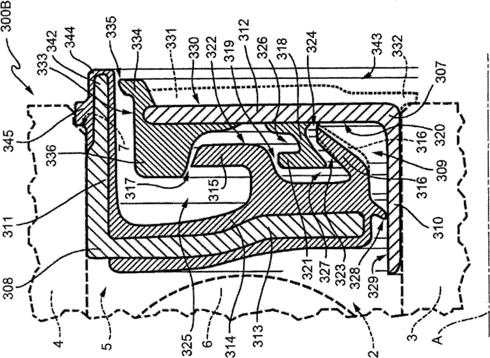
[0009] refer to figure 1 and 2 , reference number 300 ( figure 1 ) denotes a drop-type element seal, in particular it is designed to be mounted on a rolling bearing 2 of a hub assembly, which is known and not shown for the sake of clarity, and which is inserted in relative rotation between the first member 3 and the second member 4 , in the example defined by the inner ring 3 and the outer ring 4 of the bearing 2, for fluid-tight isolation from the external environment, which is indicated by the letter "E", an annular cavity 5 is defined between the members 3 and 4, and As shown in the example, it accommodates a plurality of rolling elements 6 of the bearing 2 .

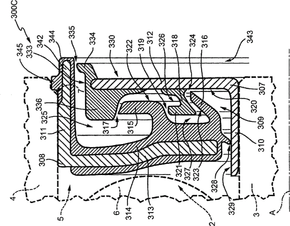
[0010] According to the first embodiment implemented as figure 1 The sealing device 300 shown, which is represented by the reference numeral 300B, and in figure 2 The second embodiment in is shown by reference numeral 300C.

[0011] For the sake of simplicity, the parts common to the two sealing devices 300B an...


PUM


Abstract

A sealing device (300B) includes a first annular shield (307) in use rotating, a second annular shield (308), in use fixed and arranged in front of the first shield for delimiting therebetween a first annular chamber (309) and a sealing ring (314) provided with first and a second annular lips (115, 116) which extend axially and radially projecting from a flange portion (313) of the second shield and towards a flange portion (312) of the first shield, inside the annular chamber. At least one of the lips (315) cooperates with the flange portion (312) of the first shield without touching it for defining a first dynamic labyrinth seal (317) therewith. The first shield integrally supports a third annular lip (318) which extends projecting from the first shield (307) towards one of the first and second lips without touching it for defining a second dynamic labyrinth seal (319) between the first and second shield (307,308) and inside the annular chamber (109). The first annular lip (315) defines a large U-shaped annular cavity (325), the second annular lip (316) defines an asymmetric V-shaped annular cavity (327) and the third I-shaped annular lip (318) defines a small U-shaped annular cavity (326) radially between the other two cavities (325, 327). Radially outward of the cavities (325, 326, 327) there are provided respective drip guard elements (337, 338, 321) which convey impurities which may have entered into the annular chamber (309) directly into the cavitiies (325, 326, and 327) and towards the exterior from the annular chamber (309).

Description

technical field [0001] The invention relates to a drop-type element seal, especially a drop-type element seal for rolling bearings. Background technique [0002] The sealing assembly intended to equip the rolling bearings of the hub assembly is formed by a so-called seal comprising a first and a second annular housing, mounted in front of each other so as to define an annular chamber between the housings, communicating towards the outside through an annular opening, and in the Said chamber, a series of sealing lips arranged in the annular chamber in substantially sliding contact on the respective sealing surfaces of the rotating housings, carried by a sealing ring integrally fixed to one of the housings, generally said housings in use stay still). One of said sealing lips arranged closest to the annular opening is usually shaped so as to define a drip element in the annular chamber, i.e. an annular groove, in which contaminated The fluid can be collected for subsequent dis...

Claims


Application Information

Patent Timeline
Patent Type & Authority Applications(China)
IPC IPC(8): F16C33/78
CPCF16C33/768F16C33/782F16C33/7883F16C33/80F16C41/007F16J15/4478F16C2326/02F16J15/3264F16C19/04B60B27/0073F16C33/76
Inventor C·格利
Owner AB SKF
Why Eureka
Try Eureka