Switch resource allocation method and switch

A technology of resource allocation and switch, applied in the field of communication, can solve problems such as system service interruption

Active Publication Date: 2018-03-16
HUAWEI TECH CO LTD
View PDF7 Cites 0 Cited by
  • Summary
  • Abstract
  • Description
  • Claims
  • Application Information

AI Technical Summary

Problems solved by technology

[0005] The present invention provides a switch resource allocation method and a switch to solve the problem of system service interruption that may be caused by switch stacking

Method used


Image

  • Switch resource allocation method and switch
  • Switch resource allocation method and switch
  • Switch resource allocation method and switch

Examples


Embodiment Construction

[0047] In order to make the purpose, technical solutions and advantages of the embodiments of the present invention clearer, the technical solutions in the embodiments of the present invention will be clearly described below in conjunction with the accompanying drawings in the embodiments of the present invention. Obviously, the described embodiments are the Some, but not all, embodiments are invented. Based on the embodiments of the present invention, all other embodiments obtained by persons of ordinary skill in the art without making creative efforts belong to the protection scope of the present invention.

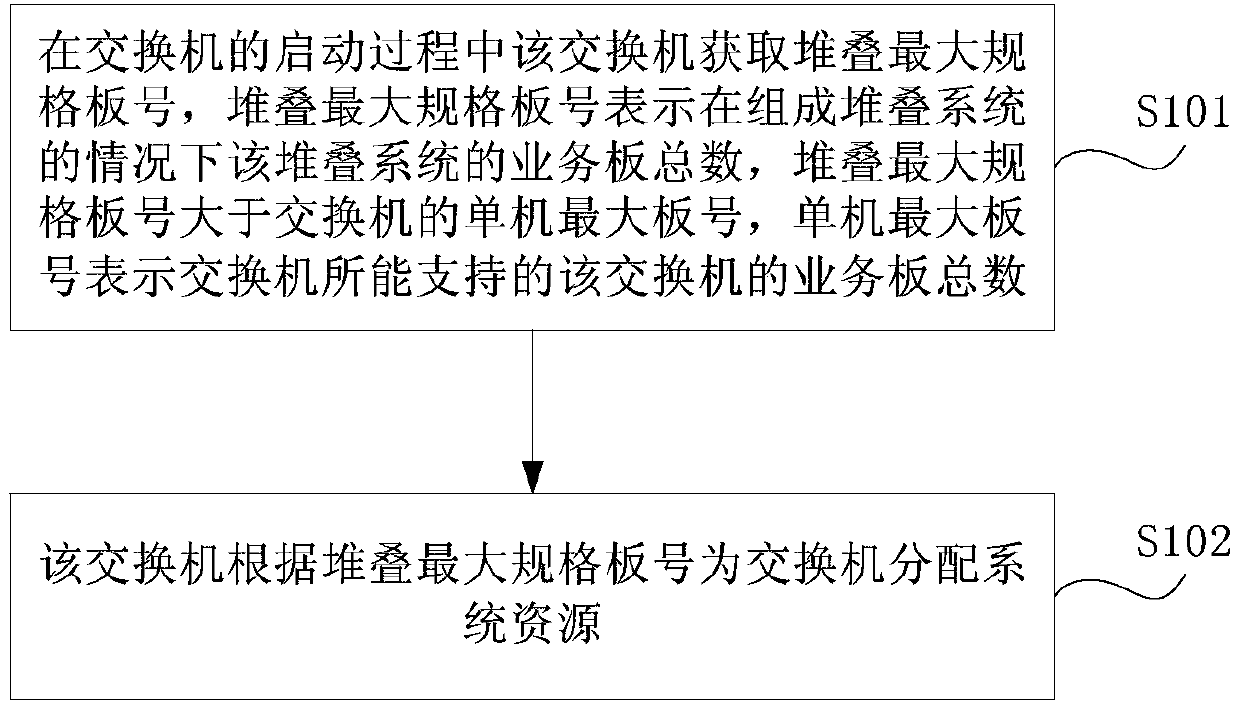
[0048] figure 1 Embodiment 1 of the present invention provides a flow chart of a switch resource allocation method. In the switch stacking system involved in this embodiment, two or more switches may be connected by stacking wires or cables (English: cable), wherein the stacking wires may be optical fibers. Two or more switches can form a star topology or a ring topol...


PUM


Abstract

The present invention provides a switch resource allocation method and a switch. By obtaining the maximum stack specification board number during the start-up process of the switch, that is, the number of service boards supported by the switch stack system in the case of forming a stack system, the maximum specification of the stack can be obtained according to the The board number allocates system resources for the switch, so that when the switch stack system is expanded and a new switch is added, it will not affect the normal business of other running switches.

Description

technical field [0001] The invention relates to communication technology, in particular to a switch resource allocation method and a switch. Background technique [0002] Switch stacking refers to a network switch, which can work independently or work together with other network switches to form a stacking system. The stacking system shows the characteristics of a single switch to the outside, but the actual port capacity is equal to all The sum of the port capacities of the member switches. [0003] Usually, start two or more switches that need to be stacked first, and then configure a stack ID for each switch. A switch in a stack system is called a member switch of the stack. The stack ID is the member number (English: member ID) of the member switch in the stack system, and is used to identify the member switch. After the stack ID is configured, enable the stack system, and connect stack cables or cables (English: cable), where the stack cables can be optical fibers. ...

Claims


Application Information

Patent Timeline
Patent Type & Authority Patents(China)
IPC IPC(8): H04L12/931H04L12/24
Inventor 刘玭娉于斌王晶
Owner HUAWEI TECH CO LTD
Why Eureka
Try Eureka