A flange assembly for connecting flue pipes

A technology for pipes and flanges, applied in the direction of pipes/pipe joints/fittings, expansion compensation devices for pipelines, pipe components, etc., can solve the problems of affecting the sealing performance of non-metallic expansion joints, poor versatility, and increased deformation. Achieve the effect of improving assembly efficiency, facilitating replacement and maintenance, and eliminating deformation

Active Publication Date: 2016-09-14
山东润驰机械科技有限公司
View PDF6 Cites 0 Cited by
  • Summary
  • Abstract
  • Description
  • Claims
  • Application Information

AI Technical Summary

Problems solved by technology

[0004] In the prior art, the metal expansion joint structure is usually used, which can indeed solve the problem of thermal expansion, but it has great limitations. Because of the reason of the mold, especially in non-standard and large-size occasions, there are high costs, Poor versatility and other deficiencies
Therefore, in the improved technical solution, a non-metallic expansion joint is used, which realizes the detachable connection with the pipe connection flange through the hole in the flange. Generally, bolts are used to penetrate the hole in the flange, but this type of structure will cause cracks. The flange part near the hole is compressed and deformed, and the deformation increases after the constant thermal expansion and contraction, which directly affects the sealing performance of the non-metallic expansion joint, resulting in adverse phenomena such as smoke leakage.

Method used


Image

  • A flange assembly for connecting flue pipes

Examples


Embodiment Construction

[0022] The present invention will be further described below with reference to the accompanying drawings.

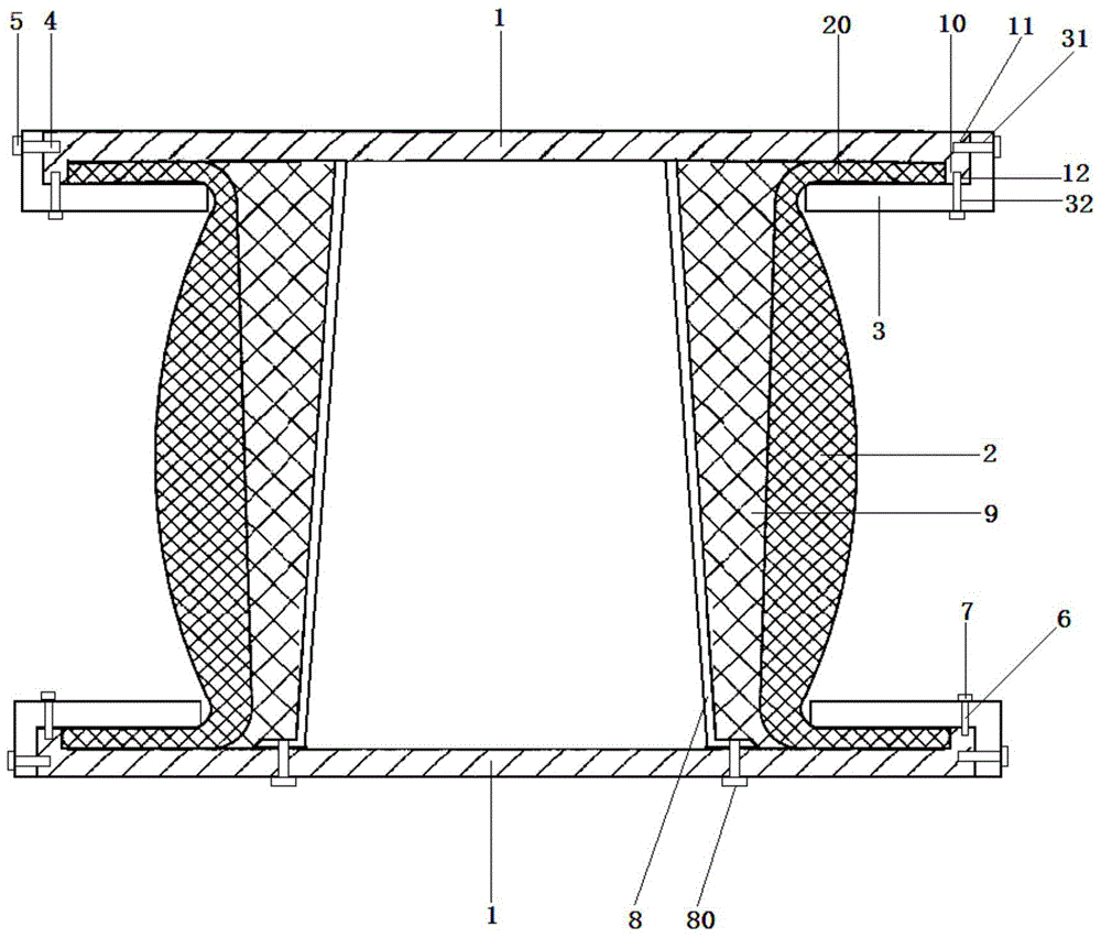
[0023] like figure 1 As shown, a flange assembly for connecting flue pipes includes flanges 1 connected to the flue pipes in pairs, non-metallic expansion joint bodies 2 arranged between the paired flanges 1, and The pressure block 3 for pressing the flange 20 of the non-metallic expansion joint body 2 and the flange 1 .

[0024] The circumference of the flange 1 is formed with the edge of the protrusion 10, the height of the protrusion 10 is equal to the thickness of the flange 20 of the non-metal expansion joint body; the side of the flange 1 is provided with pairs and uniform The first screw holes 11 are distributed; the pressing block 3 is L-shaped and has a second screw hole 31 corresponding to the first screw hole 11; the pressing block 3 passes through the first screw hole 11 and the After the second screw hole 31 is locked with a nut 5, it is connected with the...


PUM


Abstract

The invention discloses a flange assembly for connecting a flue pipe. The flange assembly comprises flanges connected to the flue pipe in pairs, nonmetallic expansion joint bodies arranged between the flanges in pairs, and pressing blocks pressing turned edges of the nonmetallic expansion joint bodies and the flanges. Protruding edges are formed in the circumferences of the flanges. The protruding height is equal to the thickness of the turned edges of the nonmetallic expansion joint bodies. First bolt holes distributed evenly in pairs are formed in the side faces of the flanges. The pressing blocks are in an L shape, and are provided with second bolt holes corresponding to the first bolt holes. The pressing blocks are connected with the flanges after first bolts penetrate through the first bolt holes and the second bolt holes to be locked through first nuts. The flange assembly is simple in structure, convenient to detach and assemble, long in service life and high in practicability, and it can be avoided that the turned edges deform during partial installation and deformation faces are expanded after use without influencing the sealing performance of the nonmetallic expansion joint bodies; the operation that holes are formed in the turned edges of the nonmetallic expansion joint bodies can be omitted, the production cost is reduced, and the assembling efficiency is greatly improved.

Description

technical field [0001] The invention relates to a pipe connecting device, in particular to a flange assembly for connecting flue pipes. Background technique [0002] The flange is the part that connects the pipe to the pipe, and is connected to the end of the pipe. Therefore, the tightness of the connection is an important parameter characteristic for testing the quality of the flange. [0003] In the boiler and its flue system, due to the thermal expansion and contraction of the thermal equipment, there are thermal displacements of different lengths between its components, which cause a lot of trouble for the positioning and support of the boiler and its flue. In order to solve this problem, the manufacturer or design unit usually considers the expansion joint structure. [0004] In the prior art, the metal expansion joint structure is usually used, which can indeed solve the problem of thermal expansion, but it has great limitations. Poor versatility and other deficienci...

Claims


Application Information

Patent Timeline
Patent Type & Authority Patents(China)
IPC IPC(8): F16L23/00F16L51/00
CPCF16L23/032F16L51/00F16L59/184F16L59/21
Inventor 陆刚强
Owner 山东润驰机械科技有限公司
Why Eureka
Try Eureka