Pipe flange

A pipeline flange and pipeline technology, which is applied in the direction of flange connection, pipe/pipe joint/pipe fitting, passing components, etc., can solve the problems of enlarged deformation surface, small fastening force, poor sealing performance, etc., and achieve stable clamping Connecting and bundling, realizing clamping and bundling, and improving assembly efficiency

Inactive Publication Date: 2015-05-13
ZHANGJIAGANG HUARI FLANGE
View PDF6 Cites 2 Cited by
  • Summary
  • Abstract
  • Description
  • Claims
  • Application Information

AI Technical Summary

Problems solved by technology

[0002] The flange is a part that connects the pipe to the pipe. It is connected to the pipe end. Therefore, the tightness of the connection is an important parameter characteristic for testing the quality of the flange. If the seal is not good, it is prone to water seepage and air leakage.
[0003] However, the bolts on the existing flange have to penetrate the entire flange and the gasket in the middle, which will cause the gasket to be deformed under pressure during installation, and the deformation surface will continue to expand during use, directly affecting the gasket. tightness
[0004] Moreover, the existing flanges are usually only fastened by bolts, the fastening force is small, and the action surface is limited to the distribution of bolts, so the entire flange cannot be subjected to a strong fastening force.

Method used


Image

  • Pipe flange
  • Pipe flange
  • Pipe flange

Examples


Embodiment Construction

[0024] Below in conjunction with accompanying drawing of description, the present invention will be further described.

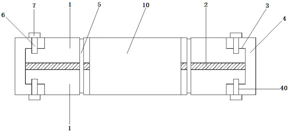
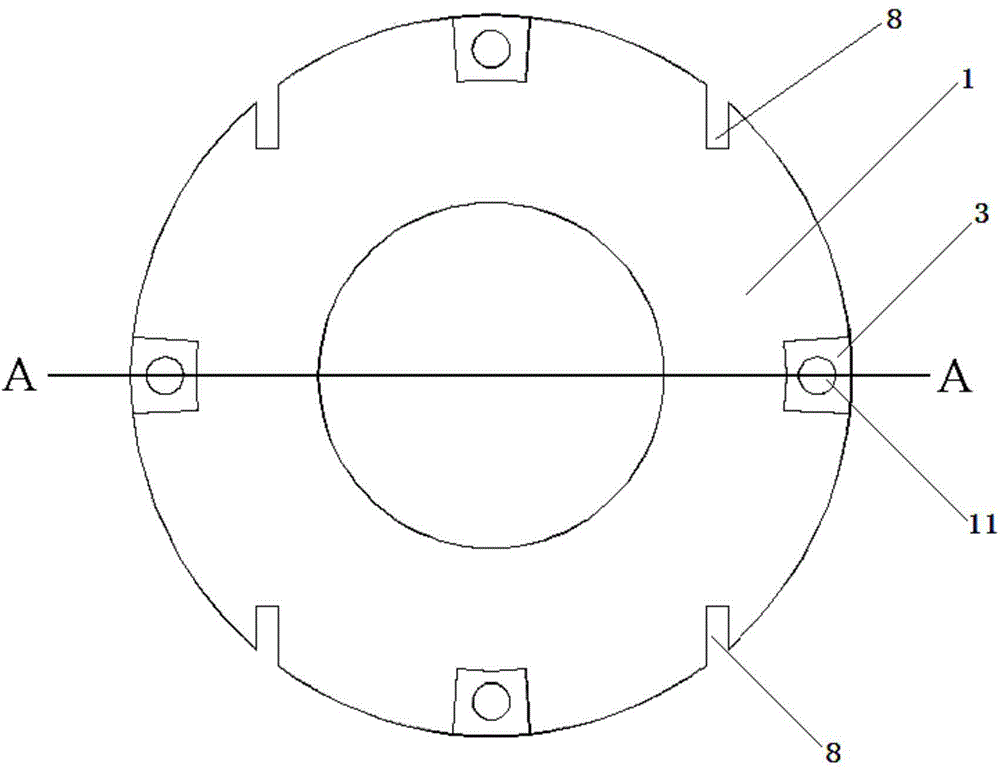
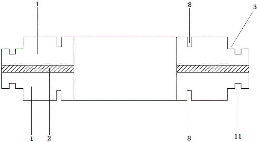
[0025] Such as figure 1 , figure 2 and image 3 A pipeline flange shown includes a pair of flanges 1 connected to the pipeline 10 and gaskets 2 between the flanges 1, and the flanges 1 are provided on the peripheral edge of the outer disk surface. There are pairs of evenly distributed notch slots 3; it also includes a side buckle pressure block 4 that clamps the paired flanges 1 from the notch slots 3, and an elastic spring that binds the paired flanges 1 from close to the pipe 10. hoop 5.

[0026] The side of the flange 1 in contact with the briquetting block 4 is provided with a first screw hole 11, and the briquetting block 4 is provided with a second screw hole 40 corresponding to the first screw hole 11, and the briquetting block 4 is passed through a screw. 6 passes through the first screw hole 11 and the second screw hole 40 and locks it with the...


PUM


Abstract

The invention discloses a pipe flange. The pipe flange comprises paired flange bodies connected to pipes and a gasket located between the flange bodies. Paired and evenly-distributed notch grooves are formed in the edge of the circumference of the outward flange face of each flange body. The pipe flange further comprises laterally-buckling type pressing blocks and elastic clamping rings, wherein the laterally-buckling type pressing blocks are arranged in the notch grooves to be used for connecting the paired flange bodies in a clamped mode, and the elastic clamping rings are arranged close to the pipes to be used for bundling the paired flange bodies. First screw holes are formed in the lateral sides, in contact with the pressing blocks, of the flange bodies, second screw holes corresponding to the first screw holes are formed in the pressing blocks, and the pressing blocks are connected with the flange bodies in the mode that screws penetrate through the first screw holes and the second screw holes to be locked through nuts. Paired concave holes are formed in the edges of the circumferences of the flange faces of the flange bodies, and the flange bodies are bundled in the mode that the two ends of the elastic clamping rings are embedded into the concave holes. The connecting straight lines of the paired concave holes keep parallel to the diameter directions of the flange bodies and close to the circumferences of the inner diameters of the flange bodies. The operation of forming holes in the gasket can be omitted, the sealing performance of the gasket is not influenced, cost is low, and assembling is rapid; dual fastening acting force is given, and efficient fastening is guaranteed.

Description

technical field [0001] The invention relates to a pipeline connection device, in particular to a pipeline flange. Background technique [0002] The flange is a part that connects the pipe to the pipe. It is connected to the pipe end. Therefore, the tightness of the connection is an important parameter characteristic for testing the quality of the flange. If the seal is not good, it is prone to water seepage and air leakage. [0003] However, the bolts on the existing flange have to penetrate the entire flange and the gasket in the middle, which will cause the gasket to be deformed under pressure during installation, and the deformation surface will continue to expand during use, directly affecting the gasket. of tightness. [0004] Moreover, the existing flanges are usually only fastened by bolts, the fastening force is relatively small, and the action surface is limited to the distribution of bolts, so the entire flange cannot be subjected to strong fastening force. Cont...

Claims


Application Information

Patent Timeline
Patent Type & Authority Applications(China)
IPC IPC(8): F16L23/032F16L23/18
CPCF16L23/032F16L23/18
Inventor 陆刚强
Owner ZHANGJIAGANG HUARI FLANGE
Why Eureka
Try Eureka