
A kind of vibrating screen with pneumatic lifting screen box

A pneumatic lifting and vibrating screen technology, which is applied in the direction of filter screen, solid separation, grille, etc., can solve the problems that affect the quality and efficiency of drilling fluid treatment by vibrating screen, the difficulty of lifting and adjusting the screen box, and the unsynchronized lifting of the screen box, etc. , to achieve the effect of simple and humanized operation, smooth and even lifting process, and guaranteed processing quality and efficiency

Active Publication Date: 2017-01-11
XIAN ZHENGDAO ENERGY MASCH EQUIP CO LTD
View PDF8 Cites 0 Cited by
  • Summary
  • Abstract
  • Description
  • Claims
  • Application Information

AI Technical Summary

Problems solved by technology

[0006] The purpose of the present invention is to provide a vibrating screen with a pneumatic lifting screen box to solve the problem that the lifting and adjusting of the screen box of the existing vibrating screen is difficult. Dealing with quality and efficiency issues

Method used


Image

  • A kind of vibrating screen with pneumatic lifting screen box
  • A kind of vibrating screen with pneumatic lifting screen box
  • A kind of vibrating screen with pneumatic lifting screen box

Examples


Embodiment Construction

[0022] The specific implementation manners of the present invention will be further described in detail below in conjunction with the accompanying drawings and examples. The following examples are used to illustrate the present invention, but are not intended to limit the scope of the present invention.

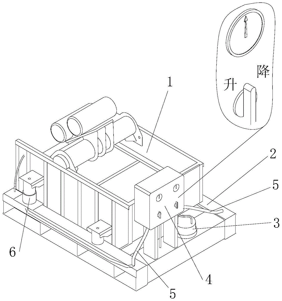
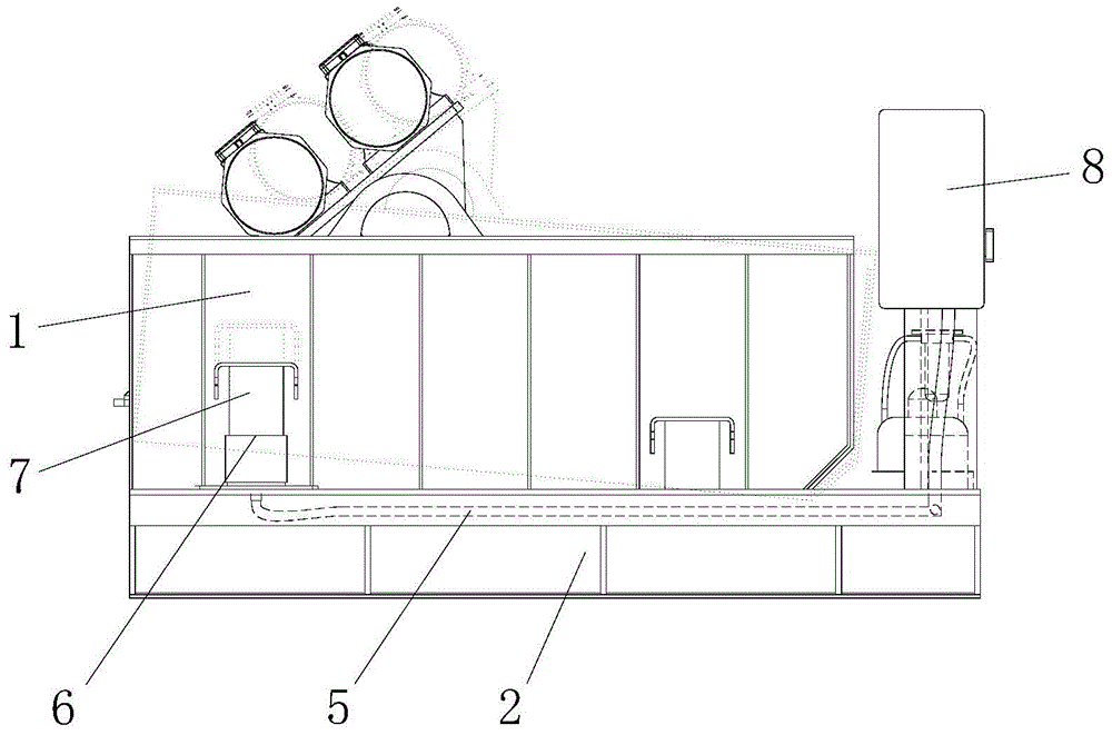
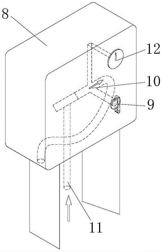
[0023] Such as figure 1 As shown, a vibrating screen for a pneumatic lifting screen box provided by the present invention includes a screen box 1, a base 2, a shock absorbing spring 7, an air source 3, a control unit 4 and an air pipe, the screen box 1 is connected to the base 2, and the air The source 3 is connected to two air pipe branches 5 through the control unit 4, and the two air pipe branches 5 are respectively arranged on both sides of the screen box 1. Connect the screen box 1, and the control unit 4 controls the on-off of the gas pipeline, so that the gas pipeline branches 5 on both sides of the screen box 1 drive the pneumatic component 6 to move up and down, and...


PUM


Abstract

The invention relates to the technical field of drilling fluid solid phase separating equipment, in particular to a vibrating screen with a pneumatic lifting screen box. The vibrating screen with the pneumatic lifting screen box comprises a screen box, a base, damping springs, an air source, a control unit and an air delivery pipe, wherein the screen box is connected with the base; the air source is connected with two air delivery pipe branches through the control unit; the two air delivery pipe branches are respectively arranged on the two sides of the screen box; each of the two air delivery pipe branches is connected with a pneumatic element; each pneumatic element is connected with the screen box through the damping spring; the on-off state of the air delivery pipe is controlled through the control unit; the pressure of air is converted into mechanical energy through the pneumatic elements; the screen box is driven to move vertically through the damping springs; the power source of the air is clean and convenient to collect; the problem of asynchronous lifting of the two sides of the conventional screen box is solved by the pneumatic lifting screen box; the operation is simple and human-friendly; the screen box is lifted stably and quickly; the inclination angle of the screen box can reach negative 1 to 5 degrees; the lifting efficiency of the screen box is improved; the treatment quality and the efficiency of the vibrating screen are guaranteed.

Description

technical field [0001] The invention relates to the technical field of drilling fluid solid-phase separation equipment, in particular to a vibrating screen for a pneumatically lifted screen box. Background technique [0002] In the fields of oil drilling, directional crossing, shield construction, etc., the drilling fluid shale shaker is the first-level solid control equipment in the drilling fluid solid phase control system. The treatment effect and service life of the solid control system are indispensable equipment in the drilling fluid solid control system. In order to adapt to different mud and different slurry feeding conditions, the vibrating screen needs to adjust the inclination angle of the screen box during the screening process. The solid phase in the drilling fluid is fully screened out, which is beneficial to the separation of the next level of solid phase. [0003] At present, the lifting of the screen box is driven by a screw and a reducer. This adjustment m...

Claims


Application Information

Patent Timeline
Patent Type & Authority Patents(China)
IPC IPC(8): B07B1/28B07B1/42
CPCB07B1/28B07B1/42
Inventor 刘越浪
Owner XIAN ZHENGDAO ENERGY MASCH EQUIP CO LTD
Learn More