

Optical fiber electric field sensor
A fiber optic electric field and sensor technology, applied in the direction of electrostatic field measurement, etc., can solve the problems of low sensor stability and reliability, easy displacement, no coupling, etc., and achieve the effect of solving structural stability problems
Inactive Publication Date: 2015-05-27
DALIAN KANGSAIPU TECH DEV
View PDF0 Cites 5 Cited by
- Summary
- Abstract
- Description
- Claims
- Application Information
AI Technical Summary
Problems solved by technology
This structure has obvious disadvantages: 1. Due to no positioning measures, the optical components are not fixed, and displacement is easy to occur; 2. Since the connection between the lens and the end face of the polarizer is suspended, the structure is unstable, and displacement is easily generated, even Falling off leads to a change in the coupling efficiency between the input lens and the output lens, or even no coupling; 3. Because the structure is not fixed, the bonding is random, and the bonding is often uneven, and the front and rear are misaligned. It is also difficult to make an ideal sensor with a five-dimensional fine-tuning instrument, and it is time-consuming
In short, the stability and reliability of the sensor with the above structure are not high, the processing technology is difficult, the production efficiency is low, and the dispersion is large.
Method used
View moreImage
Smart ImageViewing Examples

Examples
Embodiment Construction
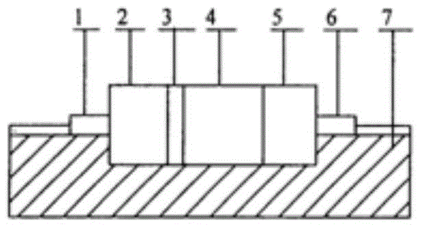
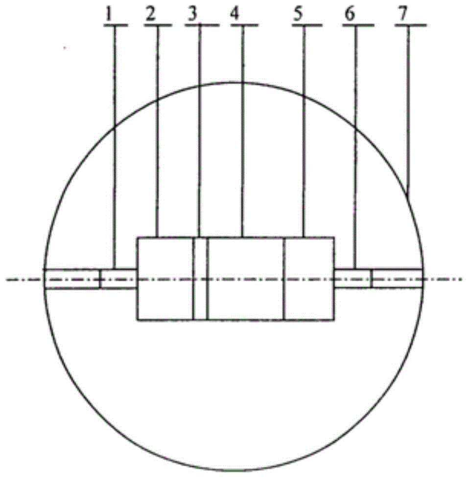
[0009] Such as figure 1 and figure 2 As shown, the collimator lens 1, polarizer 2, λ / 4 wave plate 3, electro-optic crystal 4, analyzer 5, and coupling lens 6 are sequentially placed in the groove of the plexiglass substrate 7, and bonded with optical glue, Close the upper part of the plexiglass substrate, and stick the upper and lower parts firmly to make an optical fiber electric field sensor.
Login to View More PUM
 Abstract
The invention discloses an optical fiber electric field sensor, which belongs to a photoelectric measuring device and measures an electric field based on the photoelectric effect. The optical fiber electric field sensor comprises a collimating lens, a polarizer, a Lambda / 4 wave plate, an electro-optic crystal, an analyzer, and a coupling lens, which are sequentially placed on an optical path. The optical elements are embedded onto an organic glass substrate, the organic glass substrate is provided with grooves matched with the embedded optical elements in shape and order, the optical elements are adhered together by optical adhesive, and the optical elements and the organic glass substrate are adhered together by optical adhesive. The optical elements are not easy to shift. The collimating lens and the coupling lens are on the same line in the same plane. The structure is stable. The lenses can be aligned with each other easily. The coupling efficiency is high. Connection and debugging of an optical path system are convenient. The reliability and stability of the sensor are greatly improved. The process is greatly simplified.
Description
technical field [0001] The invention belongs to a photoelectric measuring device, which measures the electric field based on the photoelectric effect. Background technique [0002] There have been many reports in the literature on the measurement of electric field based on the Pockels electro-optic effect principle. The main principle of the sensor is a collimator lens, a polarizer, a λ / 4 wave plate, an electro-optic crystal, an analyzer and a coupling lens. The process is that the light emitted by the LED is transmitted to the electric field sensor through the optical fiber, coupled into the polarizer by the collimator lens, and then the phase shift of π / 2 is generated by the λ / 4 wave plate, and then enters the electro-optic crystal. Under the action of the electric field, The light undergoes birefringence, that is, the photoelectric effect. The phase difference between the two birefringent beams is proportional to the applied electric field strength, and then the light is ...
Claims
Login to View More Application Information
Patent Timeline
 Patent Type & AuthorityApplications(China)
IPC IPC(8): G01R29/12
Inventor鞠洪建
OwnerDALIAN KANGSAIPU TECH DEV