
Electronic Input Device

An electronic input and bottom surface technology, applied in the input/output process of data processing, electrical digital data processing, instruments, etc., can solve problems such as use restrictions

Inactive Publication Date: 2015-05-27
WINTEK CORP
View PDF5 Cites 2 Cited by
  • Summary
  • Abstract
  • Description
  • Claims
  • Application Information

AI Technical Summary

Problems solved by technology

Although touch can provide a variety of inputs, the movement of this type of touch mouse in the two-dimensional direction (X-axis and Y-axis) of the plane is still realized by the movement of the entire device. Therefore, like the aforementioned general mouse, a certain amount of operating space is still required. , causing restrictions on the use of

Method used


Image

  • Electronic Input Device
  • Electronic Input Device
  • Electronic Input Device

Examples


Embodiment Construction

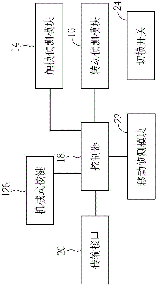
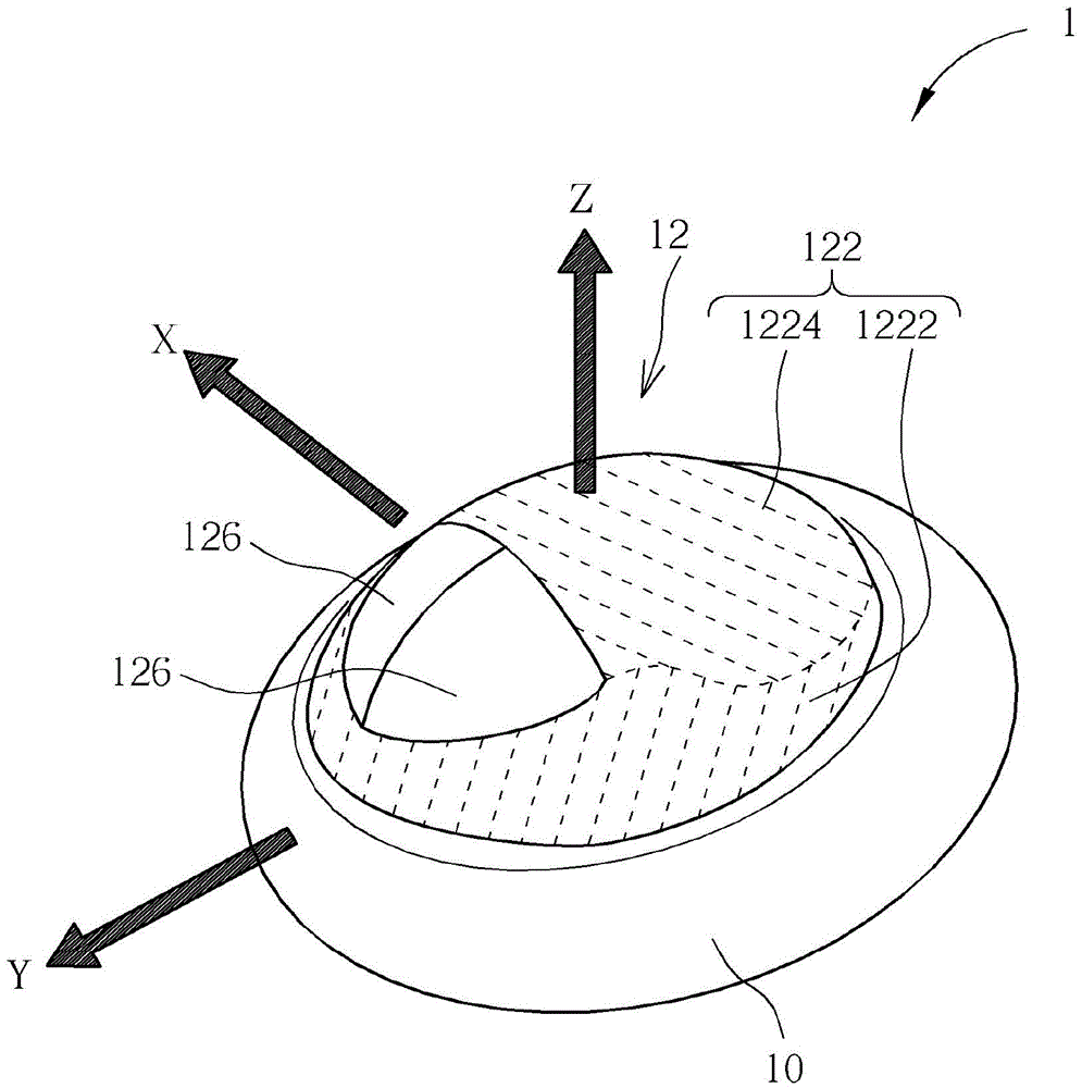
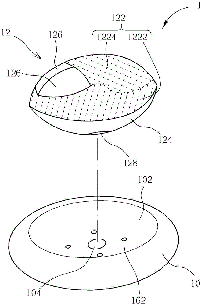
[0032] see Figure 1 to Figure 3 , figure 1 is a functional block diagram of the electronic input device 1 of the embodiment of the present invention, figure 2 is a schematic diagram of the electronic input device 1, image 3 is an exploded view of the electronic input device 1 . The electronic input device 1 includes a base 10 , an operating portion 12 , a touch detection module 14 , a rotation detection module 16 , a controller 18 and a transmission interface 20 . The base 10 has a groove 102 . The operation part 12 has a top surface 122 , a bottom surface 124 and two mechanical buttons 126 . The operating portion 12 is disposed in the groove 102 with the bottom surface 124 facing the groove 102 . The top surface 122 protrudes from the base 10 . The mechanical button 126 is disposed on the top surface 122 . The top surface 122 defines a touch area 1222 and a non-touch area 1224, indicated by dashed lines in the figure. The touch area 1222 is adjacent to the mechanic...


PUM


Abstract

An electronic input device disclosed by the present invention comprises a pedestal, an operating part, a touch detection module and a rotation detection module. The operating part possesses a top surface, a bottom surface and a key, and is arranged in a groove by using the bottom surface facing the groove of the pedestal. The top surface is protruded out of the pedestal and comprises a touch area and a non-touch area, the key is arranged on the top surface, and the touch area is adjacent to the key. The operating part can rotate relative to the pedestal, the touch detection module is arranged on the operating part to detect the touch operation in the touch area. The rotation detection module is arranged between the operating part and the pedestal to detect the rotation of the bottom surface relative to the groove. Users can place a single hand on the top surface to carry out the key, touch or rotation operation.

Description

technical field [0001] The invention relates to an electronic input device, in particular to an electronic input device with multiple input modes. Background technique [0002] A general mouse or a trackball mouse usually only provides buttons, scroll wheels, and plane movement input methods, so it usually only provides the movement function in the two-dimensional direction (X-axis and Y-axis) of the plane, and the movement in the three-dimensional direction (Z-axis) Operation can only be realized with keyboard operation. For example, if you need to zoom in and out of webpage content, in addition to clicking the function menu of the browser, another way is to press the Ctrl key on the keyboard, and then use the mouse wheel to achieve it. As another example, for drawing 3D animations and CAD models, because a general mouse or a trackball mouse cannot provide object operations in three-dimensional directions (X-axis, Y-axis and Z-axis) at the same time (such as zooming, rotat...

Claims


Application Information

Patent Timeline
IPC IPC(8): G06F3/0346G06F3/038
CPCG06F3/0346G06F3/0383
Inventor 李宗伦陈均合张友鸿
Owner WINTEK CORP
Learn More