Continuously variable device

A technology of stepless speed change and stepless speed changer, which is applied to belt/chain/gear, mechanical equipment, transmission device, etc., can solve the problems of great application prospect and no consideration of stepless speed changer.

Inactive Publication Date: 2016-08-10
王亚
View PDF1 Cites 1 Cited by
  • Summary
  • Abstract
  • Description
  • Claims
  • Application Information

AI Technical Summary

Problems solved by technology

At present, there is another type of continuously variable transmission device in which the main and driven shafts are arranged coaxially and in the same direction of rotation. The application prospect is relatively large, but the original plan did not consider this type of continuously variable transmission device.

Method used


Image

  • Continuously variable device
  • Continuously variable device
  • Continuously variable device

Examples


Embodiment Construction

[0023] specific implementation plan

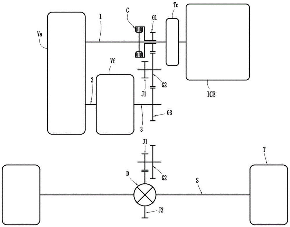
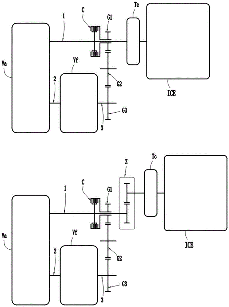
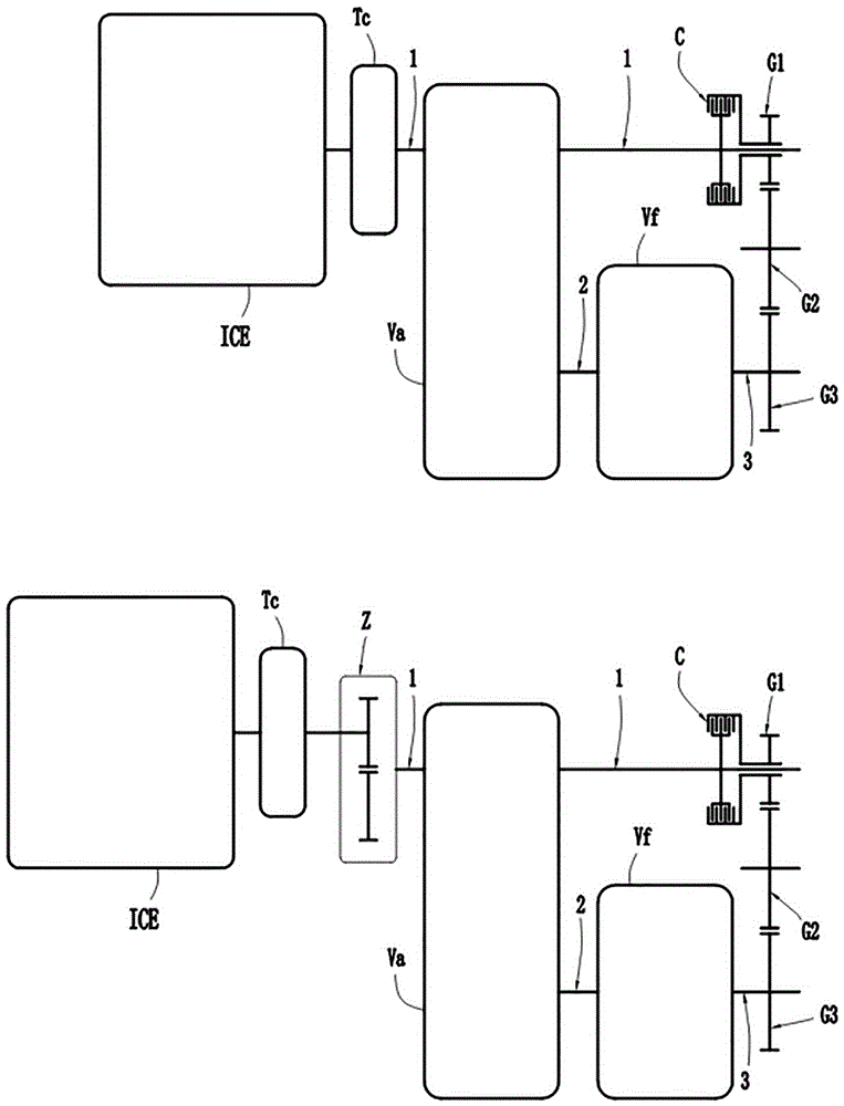
[0024]Most of the currently mass-produced continuously variable transmissions are based on a continuously variable transmission device in which the driving and driven shafts are arranged in parallel and rotate in the same direction to realize the continuously variable transmission function. For this reason, this specification firstly elaborates on the above continuously variable transmission device Va. Currently, the mass-produced mainstream continuously variable transmission Va has a range of speed ratios above 5, mostly around 6; moreover, the distance between the main and driven shafts of the continuously variable transmission Va is mostly above 100 mm. The present invention follows the method of connecting the auxiliary transmission Vf in series behind the continuously variable transmission Va, so the variable range of the speed ratio of the continuously variable transmission Va in the present invention is relatively small, about 3.

...


PUM


Abstract

The invention relates to a continuously variable transmission scheme. The driving shaft of the continuously variable transmission device is connected to the starting device by power, and the driven shaft of the continuously variable transmission device is connected to the auxiliary transmission input shaft by power. Between the drive shaft of the continuously variable transmission device and the output shaft of the auxiliary transmission, a transmission connection can be formed by two-stage spur gears. The drive gear in the two-stage gear transmission is coaxially arranged with the drive shaft of the continuously variable transmission device, and a 1 is arranged between them. A wet multi-plate clutch can engage and disengage the power connection between the driving shaft of the continuously variable transmission and the two-stage gear transmission. The driven gear in the two-stage gear transmission is arranged coaxially with the auxiliary transmission output shaft and forms a constant power connection. The driving gear and the driven gear in the two-stage gear transmission realize meshing transmission connection through an intermediate gear or an intermediate gear shaft. The auxiliary transmission is a planetary gear type, which can realize neutral gear, parking gear, 2 forward gears and 1 reverse gear through 1 internal and external meshing planetary gear. When the auxiliary transmission is in two different forward gears, the driving shaft of the continuously variable transmission and the driving gear of the two-stage gear transmission all have the same rotational speed.

Description

technical field [0001] The invention relates to a mechanical continuously variable transmission for vehicles. Background technique [0002] In the previously published CN 103527736 A, the applicant proposed a shifting method of "step transition type continuously variable transmission". The aforesaid shifting method can create favorable conditions of equal rotational speed for the shifting elements of the auxiliary transmission, so that the switching of the forward gear of the auxiliary transmission can be carried out very smoothly. However, the realization of the shifting method of "stepped transitional continuously variable transmission" must require the auxiliary transmission to be connected in series between the continuously variable transmission device and the axial space of the driven gear of the transition gear. In the aforementioned transmission scheme, in order to realize neutral gear, 2 forward gears and 1 reverse gear, the sub-transmission is mainly composed of 2 ...

Claims


Application Information

Patent Timeline
Patent Type & Authority Applications(China)
IPC IPC(8): F16H37/06
CPCF16H37/06
Inventor 王亚
Owner 王亚
Why Eureka
Try Eureka