Docking Station

A technology for expanding the base and shell, which is applied in antennas, telephone communications, instruments, etc., can solve the problem of reducing the ability of signal transmission and reception, and achieve the effect of improving the ability of signal transmission and reception

Inactive Publication Date: 2015-06-03
COMPAL ELECTRONICS INC
View PDF9 Cites 9 Cited by
  • Summary
  • Abstract
  • Description
  • Claims
  • Application Information

AI Technical Summary

Problems solved by technology

However, when the smartphone is mounted on the docking station, the antenna of the smartphone may be blocked by the shell of the docking station, which reduces the ability to transmit and receive signals.

Method used


Image

  • Docking Station
  • Docking Station
  • Docking Station

Examples


Embodiment Construction

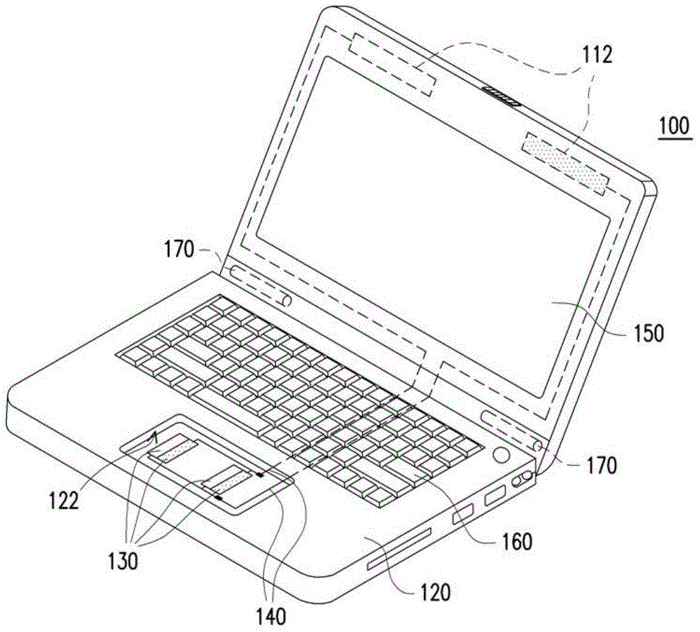
[0041] figure 1 It is a perspective view of an expansion base according to an embodiment of the present invention. Please refer to figure 1 , the docking station 100 of this embodiment includes a first housing 110 , a second housing 120 and at least one signal transmitting / receiving unit 130 (shown as a plurality). The first casing 110 has at least one first antenna 112 (multiple are shown). The second casing 120 is connected to the first casing 110 and has a groove 122 . The signal transmitting / receiving unit 130 is disposed at the bottom of the groove 122 and electrically connected to the first antenna 112 .

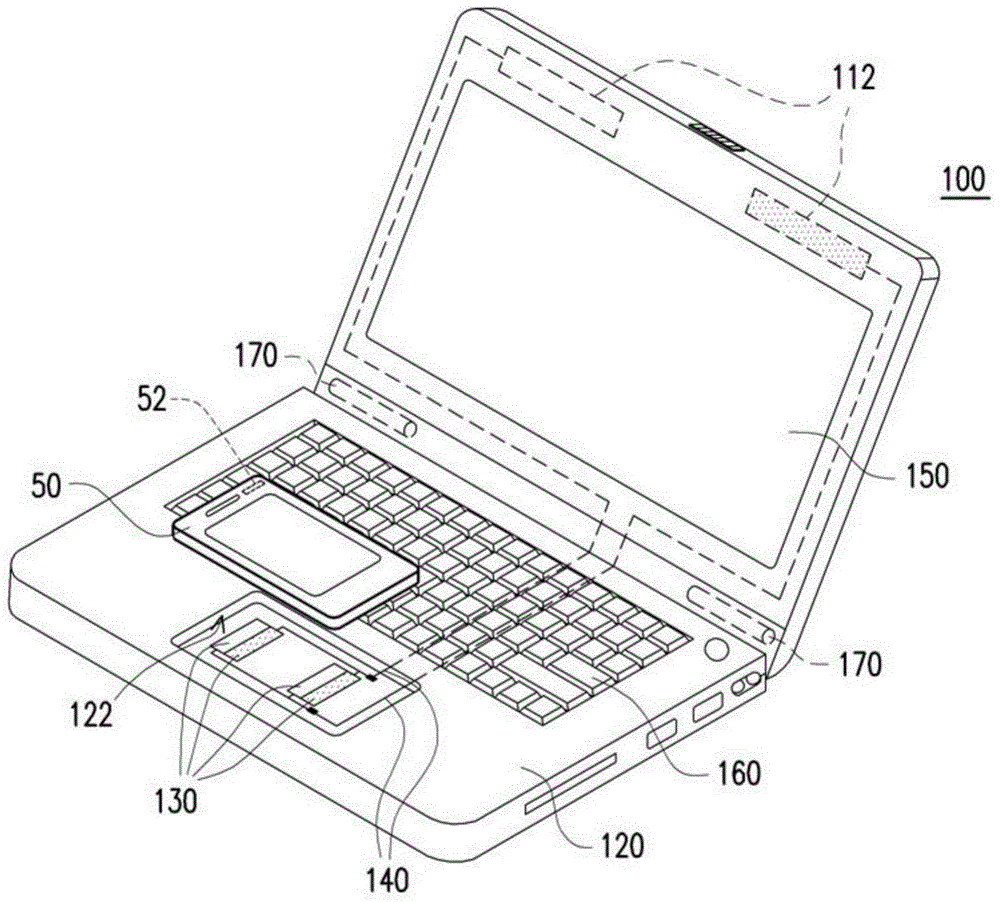
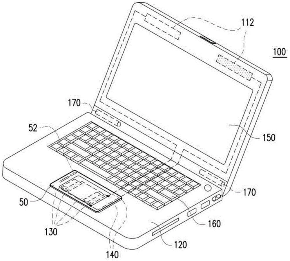
[0042] figure 2 for figure 1 Schematic diagram of the docking station detached from the electronics. image 3 for figure 2 The schematic diagram of the electronic device installed in the docking station. Figure 4 for image 3 Partial cross-sectional view of the docking station and electronic device. Please refer to Figure 2 to Figure 4 , in this embodime...


PUM


Abstract

A docking station that includes a first casing, a second casing, and a signal transmitting / receiving unit is provided. The first casing has a first antenna. The second casing is connected to the first casing and has a cavity, and the cavity is adapted to hold an electronic device. The signal transmitting / receiving unit is disposed at a bottom of the cavity and electrically connected to the first antenna. When the electronic device is held in the cavity, the electronic device receives and transmits wireless signals by the first antenna through the signal transmitting / receiving unit.

Description

technical field [0001] The present invention relates to a docking station, and more particularly to a docking station with an antenna. Background technique [0002] With the advancement of technology, the public's communication method has gradually changed to wireless communication. Handheld electronic devices such as smart phones and tablet PCs with wireless Internet access functions are all in the category of wireless communication. [0003] Taking a smart phone as an example, it usually has a small volume and weight so that users can carry it around. Generally speaking, a smart phone cannot provide users with a larger display screen and operation interface due to its small size, so a docking station that can be used in conjunction with the smart phone has been developed. The user can install the smart phone on the docking station to provide a larger display screen and operation interface (such as a keyboard) through the docking station. However, when the smart phone is ...

Claims


Application Information

Patent Timeline
Patent Type & Authority Applications(China)
IPC IPC(8): G06F1/16H04M1/72409
CPCH04M1/04H04M1/72409G06F1/1616G06F1/1626G06F1/1698H01Q1/243H01Q1/2266G06F1/1632
Inventor 张原协欧家宏欧家绮
Owner COMPAL ELECTRONICS INC
Why Eureka
Try Eureka