
Pipe bender and its control method

A control method and pipe bending machine technology, applied in the direction of manufacturing tools, feeding devices, positioning devices, etc., can solve the problem of high cost, achieve low cost, improve pipe bending efficiency, and facilitate the realization of the effect

Active Publication Date: 2016-08-24
GREE ELECTRIC APPLIANCES INC
View PDF11 Cites 0 Cited by
  • Summary
  • Abstract
  • Description
  • Claims
  • Application Information

AI Technical Summary

Problems solved by technology

[0005] The main purpose of the present invention is to provide a pipe bending machine and its control method, so as to solve the problem of high cost of the pipe bending device in the prior art to bend the pipe material left and right

Method used


Image

  • Pipe bender and its control method
  • Pipe bender and its control method
  • Pipe bender and its control method

Examples


Embodiment Construction

[0031] It should be noted that, in the case of no conflict, the embodiments in the present application and the features in the embodiments can be combined with each other. The present invention will be described in detail below with reference to the accompanying drawings and examples.

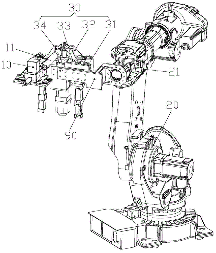
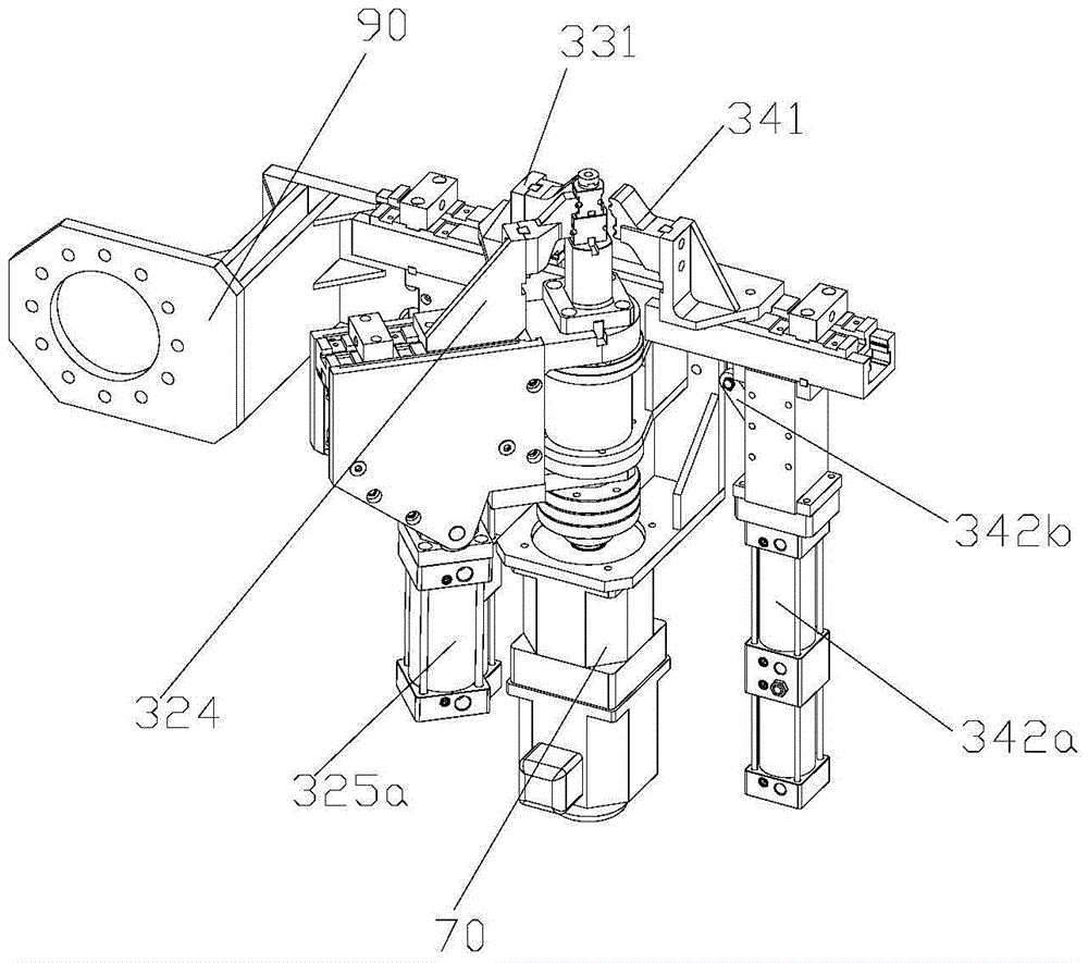
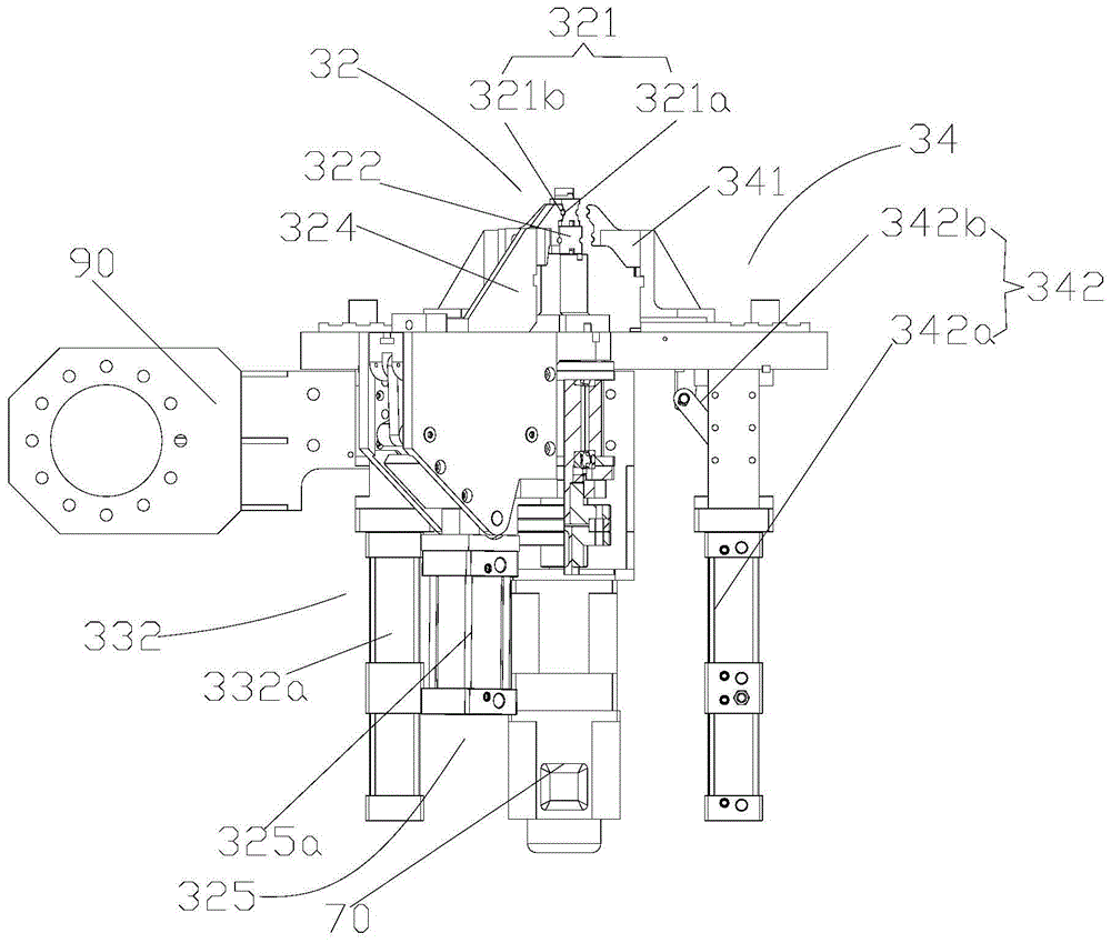
[0032] see Figure 1 to Figure 7 As shown, according to one aspect of the present invention, a pipe bending machine is provided.

[0033] In this embodiment, the pipe bending machine includes a feeding device 10 , a robot 20 and a pipe bending device 30 .

[0034] Wherein, the feeding device 10 is provided with a positioning structure 11 for locating the pipe to be bent, so as to facilitate the positioning of the pipe during the pipe bending operation; The height and horizontal direction can be set movably, so that the structure set on the support arm 21 can move freely in the space;

[0035] see figure 1 with figure 2 As shown, the pipe bending device 30 of this embodiment includes a mou...


PUM


Abstract

The invention provides a pipe bender and a control method thereof. The pipe bender comprises a feeder, a supporting arm and a pipe bending device, wherein a positioning structure for positioning a pipe to be bent is arranged on the feeder; the supporting arm is movably arranged in the horizontal direction along the height of the feeder; the pipe bending device is arranged on the supporting arm, and comprises a mounting base, a clamp assembly, a left profiling assembly and a right profiling assembly; the clamp assembly is provided with a clamping portion for clamping the pipe; the clamp assembly is rotatably mounted on the mounting base; the left profiling assembly is provided with a first pipe bending position against the clamp assembly and a first idle position far away from the clamp assembly; the right profiling assembly is provided with a second pipe bending position against the clamp assembly and a second idle position far away from the clamp assembly. The pipe bender is capable of mutually bending the pipe left and right; compared with the existing commercial pipe bending device, the pipe bender is lower in cost, and the pipe bending efficiency of the pipe bender can be improved more favorably.

Description

technical field [0001] The present invention relates to the technical field of pipe bending devices, in particular to a pipe bending machine and a control method thereof. Background technique [0002] Existing pipe bending equipment is mainly divided into two categories: the first is ordinary CNC pipe bending machines, and the second is ordinary six-axis robot pipe bending machines. [0003] Existing robot pipe benders cannot realize left and right bending at the same time, but can only achieve a single left or right bend. For complex pipe structures, it is necessary to manually weld the left and right bends together. [0004] There is also an all-in-one pipe bending machine in the prior art. During the working process, the pipe is moved from one side to the other by the robot, so as to realize the left and right mutual bending, but this method is time-consuming and expensive. expensive. Contents of the invention [0005] The main purpose of the present invention is to p...

Claims


Application Information

Patent Timeline
Patent Type & Authority Patents(China)
IPC IPC(8): B21D7/024B21D7/12B21D7/16B21C51/00B21D43/00
CPCB21C51/00B21D7/024B21D7/12B21D7/16B21D43/003
Inventor 张秀峰刘超张玉全孙继德文义平
Owner GREE ELECTRIC APPLIANCES INC
Learn More